Работаем с юридическими лицами, бюджетными организациями, ИП
По вопросам приобретения товара пишите на zakaz@lanfor.ru
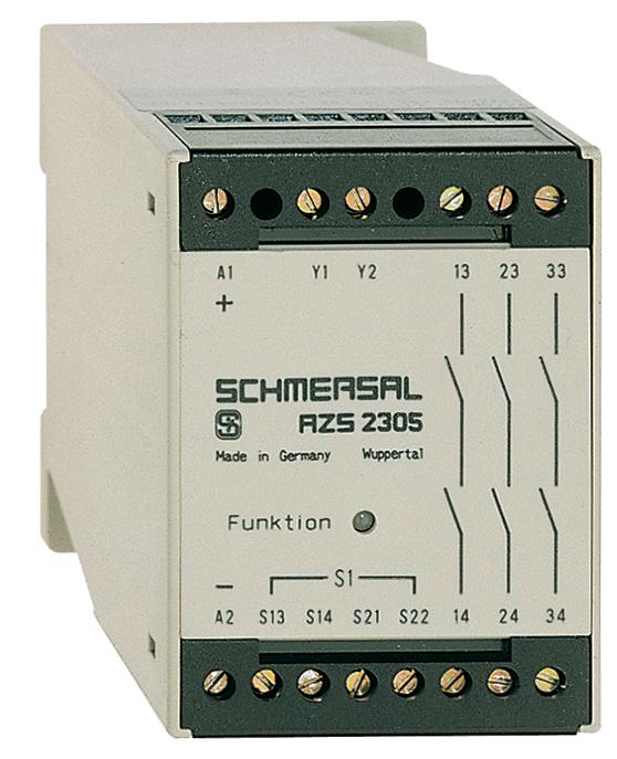
- Fail-safe delay timer
- Time adjustable from 0,1 s to 99 min
- 3 safety contacts
- 2 Signalling outputs
Ordering data
| Note (Delivery capacity) | Phased-out product |
| Product type description | AZS 2305 24 VDC |
| Article number (order number) | 101126703 |
| EAN (European Article Number) | 4030661058986 |
| eCl@ss number, Version 9.0 | 27-37-18-19 |
| eCl@ss number, Version 11.0 | 27-37-18-19 |
| ETIM number, version 6.0 | EC001449 |
| Available until | 31.12.2021 |
Approval - Standards
| Certificates | cULus EAC |
General data
| Standards | IEC/EN 60204-1 BG-GS-ET-20 EN ISO 13849-1 |
| Enclosure material | Glass-fibre, reinforced thermoplastic |
| Gross weight | 248 g |
General data - Features
| Wire breakage detection | Yes |
| Short-circuit recognition | Yes |
| Automatic reset function | Yes |
| Reset after disconnection of supply voltage | Yes |
| Earth connection detection | Yes |
| Integral System Diagnostics, status | Yes |
| Number of LEDs | 1 |
| Number of openers | 1 |
| Number of shutters | 1 |
| Number of undelayed semi-conductor outputs with signaling function | 2 |
| Number of safety contacts | 3 |
| Number of signalling outputs | 2 |
Safety appraisal
| Standards | IEC 61508 | |
| Performance level, up to | d | |
| Control category to EN13849 | 3 | |
| PFH-value | 1.00 x 10⁻⁷ /h | |
| 2 | |
| Mission Time | 20 Year(s) |
Mechanical data
| Mounting | Snaps onto standard DIN rail to EN 60715 |
Mechanical data - Connection technique
| Terminal Connector | Screw connection rigid or flexible |
| Cable section, maximum | 4 mm² |
| Note (Cable section) | All indications about the cable section are including the conductor ferrules. |
| Tightening torque of Clips | 0.4 Nm |
Mechanical data - Dimensions
| Width | 55 mm |
| Height | 75 mm |
| Depth | 110 mm |
Ambient conditions
| Degree of protection of the enclosure | IP40 |
| Degree of protection of the mounting space | IP54 |
| Degree of protection of clips or terminals | IP20 |
| Ambient temperature, minimum | +0 °C |
| Ambient temperature, maximum | +55 °C |
| Storage and transport temperature, minimum | -25 °C |
| Storage and transport temperature, maximum | +70 °C |
| Resistance to vibrations to EN 60068-2-6 | 10 ... 55 Hz, Amplitude 0.35 mm |
| Restistance to shock | 30 g / 11 ms |
Ambient conditions - Insulation value
| Rated impulse withstand voltage Uimp | 4 kV |
| Overvoltage category | III |
| Degree of pollution to VDE 0110 | 2 |
Electrical data
| Frequency range | 50 Hz 60 Hz |
| Rated operating voltage | 24 VDC ± 15 % |
| Rated AC voltage for controls at DC minimum | 20.4 VDC |
| Rated control voltage at DC, maximum | 27.6 VDC |
| Electrical power consumption | 5 W |
| Contact resistance, maximum | 0.1 Ω |
| Note (Contact resistance) | in new state |
| Drop-out delay in case of power failure, typically | 80 ms |
| Drop-out delay in case of emergency, typically | 20 ms |
| Pull-in delay at automatic start, maximum, typically | 100 ms |
| Pull-in delay at RESET, typically | 20 ms |
Electrical data - Safe relay outputs
| Voltage, Utilisation category AC15 | 250 VAC |
| Current, Utilisation category AC-15 | 2 A |
| Voltage, Utilisation category DC13 | 24 VDC |
| Current, Utilisation category DC13 | 2 A |
| Switching capacity, minimum | 10 VDC |
| Switching capacity, minimum | 10 mA |
| Switching capacity, maximum | 250 VAC |
| Switching capacity, maximum | 8 A |
Electrical data - Digital inputs
| Input signal, HIGH Signal 1 | 10 … 30 VDC |
| Input signal, LOW Signal 0 | 0 … 2 VDC |
| Conduction resistance, maximum | 40 Ω |
Electrical data - Digital Output
| Voltage, Utilisation category DC12 | 24 VDC |
| Current, Utilisation category DC12 | 0.1 A |
Electrical data - Relay outputs (auxiliary contacts)
| Switching capacity, maximum | 24 VDC |
| Switching capacity, maximum | 2 A |
Electrical data - Electromagnetic compatibility (EMC)
| EMC rating | EMC-Directive |
Integral system diagnosis (ISD)
| Note (ISD -Faults) | The following faults are registered by the safety monitoring modules and indicated by ISD. |
| Faults | Failure of the safety relay to pull-in or drop-out Fault on the input circuits or the relay control circuits of the safety monitoring module Difference in time setting between channel I and channel II Cross conclusions to the input lines Interruption of the input connections |
Other data
| Note (applications) | Fail-safe delay timer |
Notes
| Note (General) | Inductive loads (e.g. contactors, relays, etc.) are to be suppressed by means of a suitable circuit. |
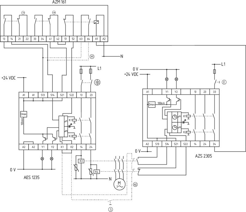
Circuit example
| Note (Wiring diagram) | The wiring diagram is shown with guard doors closed and in de-energised condition. The ISD tables (Intergral System Diagnostics) for analysis of the fault indications and their causes are shown in the appendix. To monitor one guard door at plants with dangerous run-on movements up to PL d and Category 3 Monitoring time for unlocking of solenoid interlocks The solenoid interlock releases the guard device only when the set time has elapsed. The time begins to run when the power contactors have dropped out. |
Наш менеджер свяжется с вами в ближайшее время