Работаем с юридическими лицами, бюджетными организациями, ИП
По вопросам приобретения товара пишите на zakaz@lanfor.ru
- 2 safety contacts, STOP 0
- 6 Signalling outputs
- Multi-evaluation of up to 6 safety guards
- Suitable for the signal processing of outputs with contact sensors
Ordering data
| Note (Delivery capacity) | Not available! |
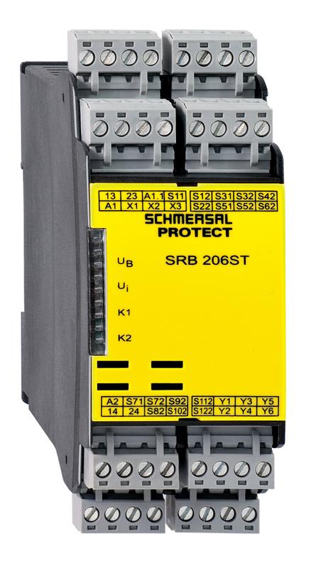
| Product type description | SRB206ST 24V AC/DC |
| Article number (order number) | 101173536 |
| EAN (European Article Number) | 4250116201853 |
| eCl@ss number, Version 9.0 | 27-37-18-19 |
| eCl@ss number, Version 11.0 | 27-37-18-19 |
| ETIM number, version 6.0 | EC001449 |
| Replacement article number | 101177165 |
Approval - Standards
| Certificates | cULus EAC |
General data
| Standards | IEC 61508 IEC/EN 60204-1 EN 60947-5-1 EN ISO 13849-1 |
| Climatic stress | EN 60068-2-78 |
| Enclosure material | Glass-fibre reinforced thermoplastic, ventilated |
| Material of the contacts, electrical | AgCdO, self-cleaning, positive drive |
| Gross weight | 250 g |
General data - Features
| Stop-Category | 0 |
| Electronic Fuse | Yes |
| Wire breakage detection | Yes |
| Removable Terminals | Yes |
| Start input | Yes |
| Feedback circuit | Yes |
| Automatic reset function | Yes |
| Reset edge detection | Yes |
| Earth connection detection | Yes |
| Integral System Diagnostics, status | Yes |
| Number of auxiliary contacts | 6 |
| Number of LEDs | 4 |
| Number of openers | 12 |
| Number of safety contacts | 2 |
| Number of signalling outputs | 6 |
Safety appraisal
| Standards | EN 60947-5-1 IEC 61508 |
Safety appraisal - Relay outputs
| Performance level, stop 0, up to | d |
| Category, Stop 0 | 3 |
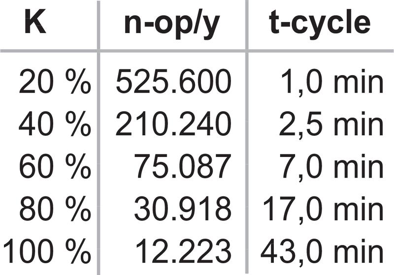
| Diagnostic Coverage (DC) Level, Stop 0 | >, 60 % |
| PFH-Value Stop 0 | 2.00 x 10⁻⁷ /h |
| Safety Integrity Level (SIL), Stop 0, suitable for applications in | 3 |
| Mission time | 20 Year(s) |
| Common Cause Failure (CCF), minimum | 65 |
Mechanical data
| Mechanical life, minimum | 10,000,000 Operations |
| Mounting | Snaps onto standard DIN rail to EN 60715 |
Mechanical data - Connection technique
| Terminal Connector | Screw connection rigid or flexible |
| Terminal designations | IEC/EN 60947-1 |
| Cable section, minimum | 0.25 mm² |
| Cable section, maximum | 2.5 mm² |
| Tightening torque of Clips | 0.6 Nm |
Mechanical data - Dimensions
| Width | 45 mm |
| Height | 100 mm |
| Depth | 121 mm |
Ambient conditions
| Degree of protection of the enclosure | IP40 |
| Degree of protection of the mounting space | IP54 |
| Degree of protection of clips or terminals | IP20 |
| Ambient temperature, minimum | -25 °C |
| Ambient temperature, maximum | +45 °C |
| Storage and transport temperature, minimum | -40 °C |
| Storage and transport temperature, maximum | +85 °C |
| Resistance to vibrations to EN 60068-2-6 | 10...55 Hz, Amplitude 0.35 mm, ± 15 % |
| Restistance to shock | 30 g / 11 ms |
Ambient conditions - Insulation value
| Rated impulse withstand voltage Uimp | 4 kV |
| Overvoltage category | III |
| Degree of pollution to VDE 0110 | 2 |
Electrical data
| Frequency range | 50 Hz 60 Hz |
| Rated operating voltage | 24 VAC -15% / +10% 24 VDC -15% / +20%, residual ripple max. 10 % |
| Operating current | 275 mA |
| Rated AC voltage for controls, 50 Hz, minimum | 20.4 VAC |
| Rated control voltage at AC 50 Hz, maximum | 26.4 VAC |
| Rated AC voltage for controls, 60 Hz, minimum | 20.4 VAC |
| Rated control voltage at AC 60 Hz, maximum | 26.4 VAC |
| Rated AC voltage for controls at DC minimum | 20.4 VDC |
| Rated control voltage at DC, maximum | 28.8 VDC |
| Utilisation category AC-15 | 230 VAC |
| Utilisation category AC-15 | 6 A |
| Utilisation category DC-13 | 24 VDC |
| Utilisation category DC-13 | 6 A |
| Electrical power consumption | 3.6 W |
| Electrical power consumption | 6.6 VA |
| Contact resistance, maximum | 0.1 Ω |
| Note (Contact resistance) | in new state |
| Drop-out delay in case of emergency stop, maximum | 30 ms |
| Pull-in delay at RESET, typically | 50 ms |
Electrical data - Digital inputs
| Conduction resistance, maximum | 40 Ω |
Electrical data - Electromagnetic compatibility (EMC)
| EMC rating | EMC-Directive |
Status indication
| Indicated operating states | Position relay K2 Position relay K1 Internal operating voltage Ui |
Other data
| Note (applications) | Guard system Emergency-Stop button Pull-wire emergency stop switches |
Notes
| Note (General) | Inductive loads (e.g. contactors, relays, etc.) are to be suppressed by means of a suitable circuit. |
Circuit example
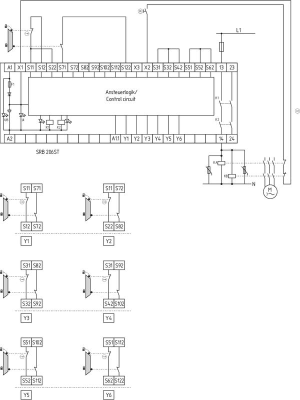
| Note (Wiring diagram) | The wiring diagram is shown with guard doors closed and in de-energised condition. Automatic start: The automatic start is programmed by connecting the feedback circuit to the terminals X1/X3. If the feedback circuit is not required, establish a bridge. Input level: The example shows a 2-channel control of a guard door monitoring with two position switches, whereof one with positive break, external reset button (R) and feedback circuit (H2). The control system recognises wire-breakage and earth faults in the monitoring circuit. Relay outputs: Suitable for 2 channel control, for increase in capacity or number of contacts by means of contactors or relays with positive-guided contacts. If more guard doors are monitored, they must be connected according to the wiring table A single failure in the sensors does not cause the safety to be lost If the single failure occurs, the safety function will be maintained. Some, although not all, errors will be recognised. An accumulation of unrecognised errors could cause the safety function to be lost. |
Наш менеджер свяжется с вами в ближайшее время