Работаем с юридическими лицами, бюджетными организациями, ИП
По вопросам приобретения товара пишите на zakaz@lanfor.ru
- Solenoid supply 24 VDC (Aux)
- Guard locking monitored
- Solenoid interlock
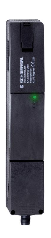
- Thermoplastic enclosure
- High holding force 2000
- 40 mm x 244 mm x 50 mm
- Interlock with protection against incorrect locking.
- Double-insulated
- Long life
- Integrated AS-Interface
Ordering data
| Note (Delivery capacity) | Phased-out product |
| Product type description | AZM 200ST-T-AS AP |
| Article number (order number) | 101190948 |
| EAN (European Article Number) | 4030661356433 |
| eCl@ss number, Version 9.0 | 27-27-26-03 |
| eCl@ss number, Version 11.0 | 27-27-26-03 |
| Available until | 31.12.2020 |
Approval - Standards
| Certificates | TÜV cULus ASi-SaW EAC |
General data
| Standards | IEC 61508 IEC 60947-5-3 EN 60947-5-1 EN 62026-2 EN ISO 13849-1 |
| general information | Universal coding |
| Coding level according to ISO 14119 | Low |
| Active principle | electromechanical |
| Enclosure material | Plastic, glass-fibre reinforced thermoplastic, self-extinguishing |
| Gross weight | 523 g |
| Time to readiness, maximum | 4,000 ms |
| Reaction time, maximum | 60 ms |
| Duration of risk, maximum | 120 ms |
General data - Features
| Power to lock | Yes |
| Guard locking monitored | Yes |
| Integral System Diagnostics, status | Yes |
| Number of actuating directions | 1 |
Safety appraisal
| Standards | IEC 60947-5-3 IEC 61508 | |
| Performance level, up to | e | |
| Control category to EN13849 | 4 | |
| PFH-value | 4.00 x 10⁻⁹ /h | |
| 3 | |
| Mission Time | 20 Year(s) |
Mechanical data
| Mechanical life, minimum | 1,000,000 Operations |
| Clamping force | 2,000 N |
| Latching force | 30 N |
| Actuating speed, maximum | 2 m/s |
| Tightening torque of the screw, maximum | 1 Nm |
Mechanical data - Connection technique
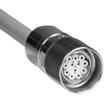
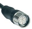
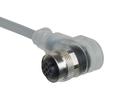
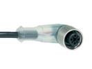
| Terminal Connector | Connector plug M12, 4-pole, (A-coding) |
Mechanical data - Dimensions
| Length of sensor | 50 mm |
| Width of sensor | 40 mm |
| Height of sensor | 244 mm |
Ambient conditions
| Degree of protection | IP67 to EN 60529 |
| Ambient temperature, minimum | -25 °C |
| Ambient temperature, maximum | +60 °C |
| Storage and transport temperature, minimum | -25 °C |
| Storage and transport temperature, maximum | +85 °C |
| Relative humidity, minimum | 30 % |
| Relative humidity, maximum | 95 % |
| Note (Relative humidity) | non-condensing |
| Resistance to vibrations to EN 60068-2-6 | 10 Hz ... 150 Hz, amplitude 0.35 mm |
| Restistance to shock | 30 g / 11 ms |
| Protection rating | II |
Ambient conditions - Insulation value
| Rated insulation voltage Ui | 32 VDC |
| Rated impulse withstand voltage Uimp | 0.8 kV |
| Overvoltage category | III |
| Degree of pollution to VDE 0100 | 3 |
Electrical data - AS Interface
| AS-i Operating voltage, minimum | 26.5 VDC |
| AS-i Operating voltage AS-i maximum | 31.6 VDC |
| Note (AS-i Operating voltage) | Protection against polarity reversal |
| AS-i Current consumption, maximum | 100 mA |
Electrical data - AS-Interface specification
| AS-i Specification | Safety-Slave |
| AS-i Version | V 2.1 |
| AS-i Profile | S-7.B.F.E |
| AS-i, IO-Code | 0x7 |
| AS-i, ID-Code | 0xB |
| AS-i, ID-Code1 | 0xF |
| AS-i, ID-Code2 | 0xE |
| AS-i Input, Channel 1 | Data bits DI 0 / DI 1 = dynamic code transmission |
| AS-i Input, Channel 2 | Data bits DI 2 / DI 3 = dynamic code transmission |
| AS-i Outputs, DO 0 | Solenoid control |
| AS-i Outputs, DO 1 | No Function |
| AS-i Outputs, DO 2 | No Function |
| AS-i Outputs, DO 3 | No Function |
| AS-i Parameter bits, P0 | Safety guard and actuator detected |
| AS-i Parameter bits, P1 | Solenoid interlock locked |
| AS-i Parameter bits, P2 | Magnet voltage in tolerance range |
| AS-i Parameter bits, P3 | Error |
| Note (AS-i Parameter bits) | Set the parameter outputs to '1111' (0xF) FID: periphery error |
| AS-i Input module address | 0 |
| Note (AS-i Input module address) | Preset to address 0, can be changed through AS-interface bus master or hand-held programming device |
Electrical data - Auxiliary voltage
| Rated operating voltage | 24 VDC -15% / +10% (stabilised PELV) |
| Operating current | 500 mA |
Status indication
| Note (LED switching conditions display) | (1) LED green-red (AS-i Duo LED): Supply voltage / Communication error / Slave address = 0 (2) LED red: Internal device error (3) LED yellow: Device condition |
Other data
| Note (applications) | sliding safety guard removable guard hinged safety guard |
Pin assignment
| PIN 1 | AS-i + |
| PIN 2 | Aux - (P) |
| PIN 3 | AS-Interface - |
| PIN 4 | Aux + (P) |
Scope of delivery
| Included in delivery | Actuators must be ordered separately. |
Notes
| Note (General) | Interlocks with the power to lock principle may only be used in special cases after a thorough evaluation of the accident risk, since the guarding device can immediately be opened on failure of the electrical power supply or when the main switch is opened. |
Наш менеджер свяжется с вами в ближайшее время