Работаем с юридическими лицами, бюджетными организациями, ИП
По вопросам приобретения товара пишите на zakaz@lanfor.ru
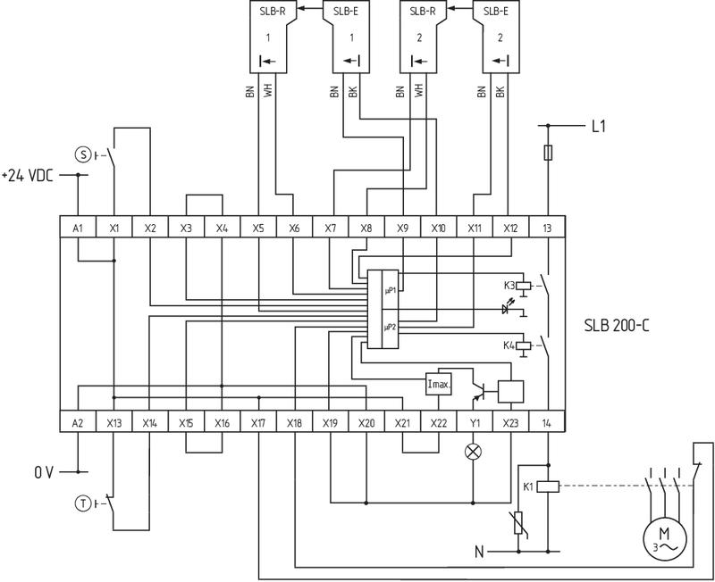
- Up to 2 light barrier pairs SLB 200 can be connected
- 1 safety contact
- 1 Signalling output
Ordering data
| Note (Delivery capacity) | Not available! |
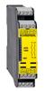
| Product type description | SLB 200-C04-1R |
| Article number (order number) | 101138897 |
| EAN (European Article Number) | 4030661281537 |
| eCl@ss number, Version 9.0 | 27-37-18-19 |
| eCl@ss number, Version 11.0 | 27-37-18-19 |
| ETIM number, version 6.0 | EC001449 |
General data
| Standards | IEC/EN 61496-1/-2 EN ISO 13849-1 |
| Enclosure material | Glass-fibre, reinforced thermoplastic |
| Gross weight | 350 g |
| Time to readiness, maximum | 300 ms |
| Reaction time, maximum | 30 ms |
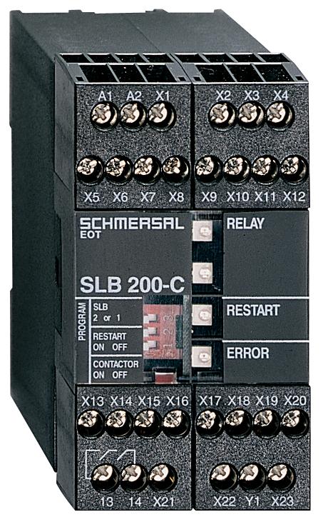
General data - Features
| Start input | Yes |
| Feedback circuit | Yes |
| Automatic reset function | Yes |
| Reset edge detection | Yes |
| Integral System Diagnostics, status | Yes |
| Number of LEDs | 4 |
| Number of safety contacts | 1 |
| Number of signalling outputs | 1 |
Safety appraisal
| Standards | IEC 61508 | |
| Performance level, up to | d | |
| Control category to EN13849 | 2 | |
| 2 | |
| Mission Time | 20 Year(s) |
Mechanical data
| Mounting | Snaps onto standard DIN rail to EN 60715 |
Mechanical data - Connection technique
| Terminal Connector | Screw connection |
| Cable section, maximum | 4 mm² |
| Note (Cable section) | All indications about the cable section are including the conductor ferrules. |
Mechanical data - Dimensions
| Width | 45 mm |
| Height | 84 mm |
| Depth | 118 mm |
Ambient conditions
| Degree of protection of the enclosure | IP40 |
| Degree of protection of the mounting space | IP54 |
| Degree of protection of clips or terminals | IP20 |
| Ambient temperature, minimum | +0 °C |
| Ambient temperature, maximum | +50 °C |
| Storage and transport temperature, minimum | -20 °C |
| Storage and transport temperature, maximum | +80 °C |
| Resistance to vibrations to EN 60068-2-6 | 10 ... 55 Hz, Amplitude 0.35 mm |
| Restistance to shock | 10 g / 16 ms |
Ambient conditions - Insulation value
| Rated impulse withstand voltage Uimp | 4.8 kV |
| Overvoltage category | II |
| Degree of pollution to VDE 0110 | 3 |
Electrical data
| Rated operating voltage | 24 VDC ±20% |
| Operating current | 180 mA |
| Utilisation category AC-15 | 250 VAC |
| Utilisation category AC-15 | 2 A |
| Utilisation category DC-13 | 24 VDC |
| Utilisation category DC-13 | 2 A |
| Switching frequency, maximum | 10 Hz |
Electrical data - Electromagnetic compatibility (EMC)
| EMC rating | EMC-Directive |
Status indication
| Indicated operating states | RELAY, green: safety contact closed RELAY, red: safety contact open |
Other data
| Note (applications) | Safety light barriers |
Notes
| Note (General) | Inductive loads (e.g. contactors, relays, etc.) are to be suppressed by means of a suitable circuit. In order to set for the desired mode of operation and number of light barriers connected, remove the front cover of the safety monitoring module. As supplied all switches are in Position 1. The required functions can be selected by means of the internal DIP switches. Test push button (T): The test push button is connected to X13 and X14 in order to carry out a check of the light barrier monitoring function. The terminals X15 and X16 must be bridged. |
| DIP switch 1, Position 1 | With contactor control |
| DIP switch 1, Position 2 | Without contactor control |
| DIP switch 2, Position 1 | With start-/restart interlock |
| DIP switch 2, Position 2 | Without start-/restart interlock |
| DIP switch 3, Position 1 | Connection of 2 light barrier(s) |
| DIP switch 3, Position 2 | Connection of 1 light barrier(s) |
Circuit example
| Note (Wiring diagram) | The wiring diagram is shown for the de-energised condition. Monitoring up to two pairs of light barrier devices and the power contactors using the SLB 200-C safety monitoring module Contactor check: To monitor an external contactor, the feedback circuit is connected to X17 and X18. The terminals X19 and X20 must be bridged. Start push button (S): The start push button can be used to start the monitoring of the light barriers for a new start or after an interruption. The terminals X3 and X4 must be bridged. It is also possible to connect only one pair of light barrier devices. |
Наш менеджер свяжется с вами в ближайшее время