Работаем с юридическими лицами, бюджетными организациями, ИП
По вопросам приобретения товара пишите на zakaz@lanfor.ru
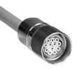
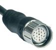
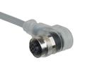
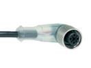
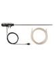
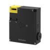
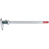
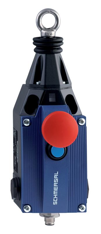
- AS-Interface M12 connector, bottom, can be rotated
- with Emergency-Stop button
- Metal enclosure
- one-side operation / wire up to 75 m long
- Release push button
- Position indicator
- Robust design
- Twisting of towing eye not possible
- External watertight collar
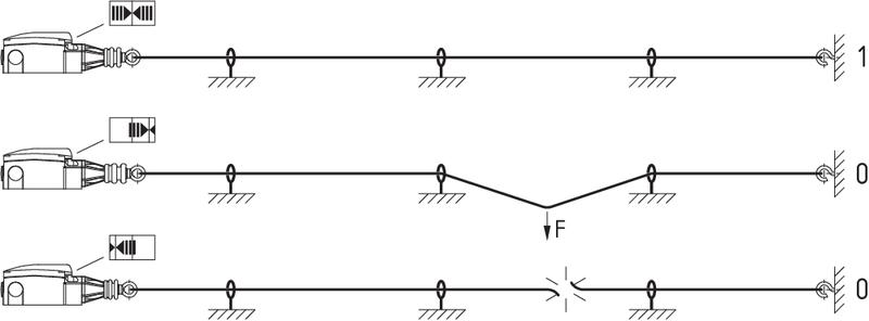
- wire pull and breakage detection
- Integrated AS-Interface
- Suitable for AS-i Power24
Ordering data
| Note (Delivery capacity) | Phased-out product |
| Product type description | ZQ 900 ST-AS N |
| Article number (order number) | 101214840 |
| EAN (European Article Number) | 4030661404462 |
| eCl@ss number, Version 9.0 | 27-37-12-01 |
| eCl@ss number, Version 11.0 | 27-37-12-01 |
| ETIM number, version 6.0 | EC002026 |
| Available until | 31.12.2020 |
Approval - Standards
| Certificates | cULus ASi-SaW EAC |
General data
| Standards | IEC 61508 EN 60947-5-1 EN 50295 EN ISO 13850 EN ISO 13849-1 |
| Enclosure material | Zinc die-cast, paint finish |
| Enclosure coating material | painted |
| Material of the cover | Plastic, glass-fibre reinforced thermoplastic, self-extinguishing |
| Length of the wire, maximum | 50 m |
| Gross weight | 1,365 g |
| Reaction time, maximum | 100 ms |
General data - Features
| Emergency-Stop button | Yes |
Safety appraisal
| Standards | IEC 61508 | |
| Performance level, up to | e | |
| Control category to EN13849 | 4 | |
| PFH-value | 1.40 x 10⁻⁸ /h | |
| Note (PFH-value) | up to max. 5,000 switching cycles/year | |
| 3 | |
| Mission Time | 20 Year(s) |
Mechanical data
| Mechanical life, minimum | 100,000 Operations |
| Actuating force, maximum | 200 N |
| Actuating travel | 400 mm |
Mechanical data - Connection technique
| Terminal Connector | Connector plug M12, 4-pole, (A-coding) |
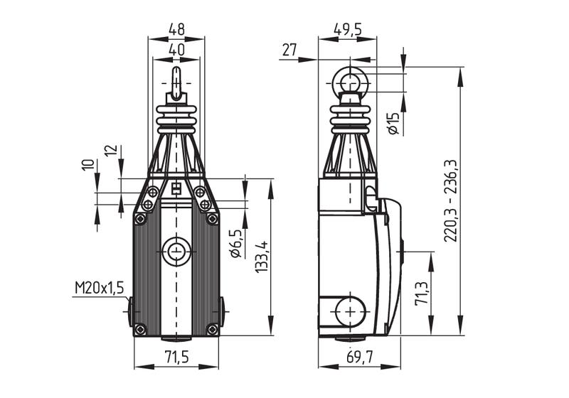
Mechanical data - Dimensions
| Length of sensor | 97 mm |
| Width of sensor | 71.5 mm |
| Height of the Sensor, minimum | 220.3 mm |
| Height of the Sensor, maximum | 236.3 mm |
Ambient conditions
| Degree of protection | IP65 IP67 to EN 60529 |
| Ambient temperature, minimum | -25 °C |
| Ambient temperature, maximum | +60 °C |
| Storage and transport temperature, minimum | -25 °C |
| Storage and transport temperature, maximum | +85 °C |
| Relative humidity, minimum | 30 % |
| Relative humidity, maximum | 95 % |
| Note (Relative humidity) | non-condensing non-icing |
| Resistance to vibrations to EN 60068-2-6 | 10 … 150 Hz, amplitude 0.35 mm 10 … 150 Hz, with 5 g |
| Restistance to shock | 15 g / 11 ms |
Ambient conditions - Insulation value
| Rated insulation voltage Ui | 32 V |
| Rated impulse withstand voltage Uimp | 0.8 kV |
| Overvoltage category | III |
| Degree of pollution to VDE 0100 | 3 |
Electrical data
| Operating Current | 50 mA |
| Switching principle | Snap switch element |
| Switching frequency | 3,600 /h |
Electrical data - AS Interface
| AS-i Operating voltage, minimum | 18 VDC |
| AS-i Operating voltage AS-i maximum | 31.6 VDC |
| Note (AS-i Operating voltage) | Protection against polarity reversal |
Electrical data - AS-Interface specification
| AS-i Version | V 3.0 |
| AS-i Profile | S-0.B.F.F |
| AS-i, IO-Code | 0x0 |
| AS-i, ID-Code | 0xB |
| AS-i, ID-Code1 | 0xF |
| AS-i, ID-Code2 | 0xF |
| AS-i Input, Channel 1 | Data bits DI 0 / DI 1 = dynamic code transmission |
| AS-i Input, Channel 2 | Data bits DI 2 / DI 3 = dynamic code transmission |
| AS-i Outputs, DO 0 … DO 3 | No Function |
| AS-i Parameter bits, P0 | Channel 2 switched |
| AS-i Parameter bits, P1 | No function |
| AS-i Parameter bits, P2 | No function |
| AS-i Parameter bits, P3 | No function |
| Note (AS-i Parameter bits) | Set the parameter outputs to '1111' (0xF) FID: periphery error |
| AS-i Input module address | 0 |
| Note (AS-i Input module address) | Preset to address 0, can be changed through AS-interface bus master or hand-held programming device |
Pin assignment
| PIN 1 | AS-Interface + |
| PIN 2 | n.c. |
| PIN 3 | AS-Interface - |
| PIN 4 | n.c. |
| PIN 5 | Functional earth connection |
Notes
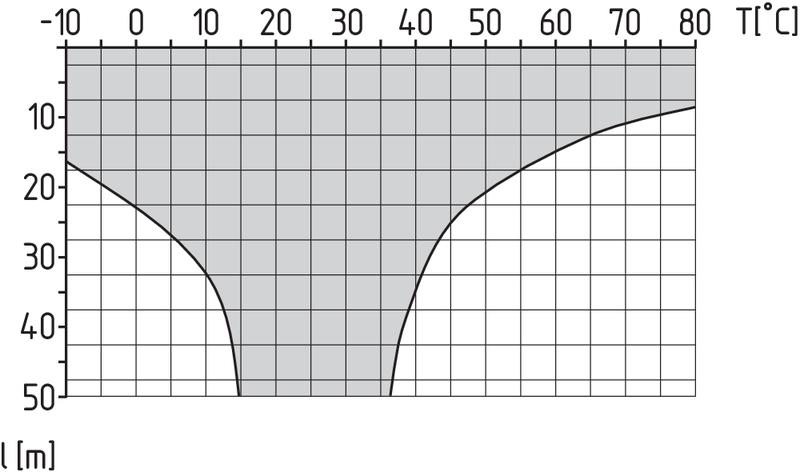
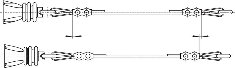
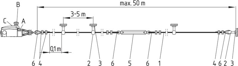
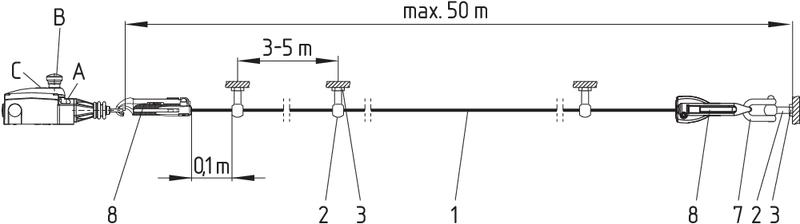
| Note (General) | Recommended cable lengths for pull-wire Emergency-Stop switches in relation to the range of ambient temperature. As the thimbles are subject to deformation in case of wire pull, the wire should be pulled several times after fitting. After that, the wire must be re-tensioned using the eyebolt or the tensioner. The addressing must take place via the M12 connector or the flat cable connection. At 5 m distance intermediate wire supports are required, see accessories |
Наш менеджер свяжется с вами в ближайшее время