Работаем с юридическими лицами, бюджетными организациями, ИП
По вопросам приобретения товара пишите на zakaz@lanfor.ru
- Monitoring of BNS range magnetic safety sensors
- 1 safety contact, STOP 0
Ordering data
| Note (Delivery capacity) | Phased-out product |
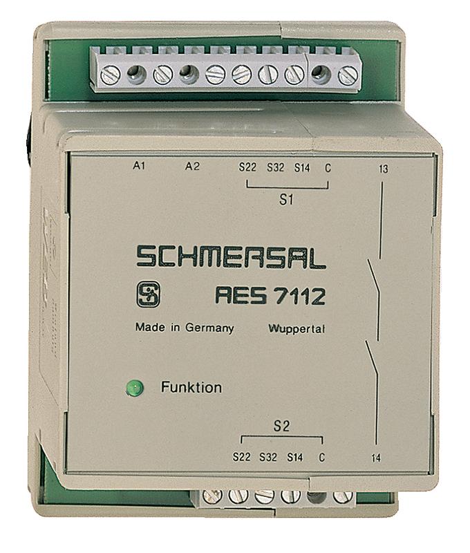
| Product type description | AES 7112.1 110 VAC |
| Article number (order number) | 101115497 |
| EAN (European Article Number) | 4030661058467 |
| eCl@ss number, Version 9.0 | 27-37-18-19 |
| eCl@ss number, Version 11.0 | 27-37-18-19 |
| ETIM number, version 6.0 | EC001449 |
Approval - Standards
| Certificates | BG cULus EAC |
General data
| Standards | IEC/EN 60204-1 IEC 60947-5-3 BG-GS-ET-14 BG-GS-ET-20 EN ISO 13849-1 |
| Enclosure material | Glass-fibre reinforced thermoplastic, ventilated |
| Material of the contacts, electrical | AgSn0 |
| Gross weight | 236 g |
General data - Features
| Stop-Category | 0 |
| Wire breakage detection | Yes |
| Short-circuit recognition | Yes |
| Automatic reset function | Yes |
| Reset after disconnection of supply voltage | Yes |
| Integral System Diagnostics, status | Yes |
| Number of LEDs | 1 |
| Number of openers | 2 |
| Number of shutters | 4 |
| Number of safety contacts | 1 |
Safety appraisal
| Standards | EN ISO 13849-1 IEC 61508 |
Safety appraisal - Relay outputs
| Performance Level, up to | d |
| Control category to EN13849 | 3 |
| PFH-value | 1.00 x 10⁻⁷ /h |
| Notice | for max. 50,000 switching cycles/year and max. 80% contact load |
| Safety Integrity Level (SIL), suitable for applications in | 2 |
| Mission time | 20 Year(s) |
Mechanical data
| Mechanical life, minimum | 3,000,000 Operations |
| Mounting | Snaps onto standard DIN rail to EN 60715 |
Mechanical data - Connection technique
| Terminal Connector | Screw connection rigid or flexible |
| Cable section, maximum | 1.5 mm² |
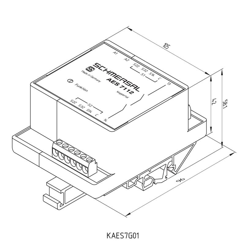
Mechanical data - Dimensions
| Width | 105 mm |
| Height | 96 mm |
| Depth | 58 mm |
Ambient conditions
| Degree of protection of the enclosure | IP40 |
| Degree of protection of the mounting space | IP54 |
| Degree of protection of clips or terminals | IP20 |
| Ambient temperature, minimum | +0 °C |
| Ambient temperature, maximum | +55 °C |
| Storage and transport temperature, minimum | -25 °C |
| Storage and transport temperature, maximum | +70 °C |
| Resistance to vibrations to EN 60068-2-6 | 10...55 Hz, Amplitude 0.35 mm, ± 15 % |
| Restistance to shock | 30 g / 11 ms |
Ambient conditions - Insulation value
| Rated impulse withstand voltage Uimp | 4 kV |
| Overvoltage category | III |
| Degree of pollution to IEC/EN 60664-1 | 2 |
Electrical data
| Frequency range | 50 Hz 60 Hz |
| Thermal test current | 5 A |
| Rated operating voltage | 110 VAC |
| Rated AC voltage for controls, 50 Hz, minimum | 93.5 VAC |
| Rated control voltage at AC 50 Hz, maximum | 121 VAC |
| Rated AC voltage for controls, 60 Hz, minimum | 93.5 VAC |
| Rated control voltage at AC 60 Hz, maximum | 121 VAC |
| Electrical power consumption | 1.5 W |
| Contact resistance, maximum | 0.1 Ω |
| Note (Contact resistance) | in new state |
| Drop-out delay in case of power failure, typically | 80 ms |
| Drop-out delay in case of emergency, typically | 20 ms |
| Pull-in delay at automatic start, maximum, typically | 100 ms |
| Pull-in delay at RESET, typically | 20 ms |
Electrical data - Safe relay outputs
| Voltage, Utilisation category AC15 | 250 VAC |
| Current, Utilisation category AC-15 | 2 A |
| Voltage, Utilisation category DC13 | 24 VDC |
| Current, Utilisation category DC13 | 2 A |
| Switching capacity, minimum | 10 VDC |
| Switching capacity, minimum | 10 mA |
| Switching capacity, maximum | 250 VAC |
| Switching capacity, maximum | 8 A |
Electrical data - Digital inputs
| Conduction resistance, maximum | 40 Ω |
Electrical data - Digital Output
| Voltage, Utilisation category DC12 | 24 VDC |
| Current, Utilisation category DC12 | 0.1 A |
Electrical data - Relay outputs (auxiliary contacts)
| Switching capacity, maximum | 24 VDC |
| Switching capacity, maximum | 2 A |
Electrical data - Electromagnetic compatibility (EMC)
| EMC rating | EMC-Directive |
Status indication
| Indicated operating states | Authorised operation |
Other data
| Note (applications) | Safety sensor Guard system |
Notes
| Note (General) | Inductive loads (e.g. contactors, relays, etc.) are to be suppressed by means of a suitable circuit. |
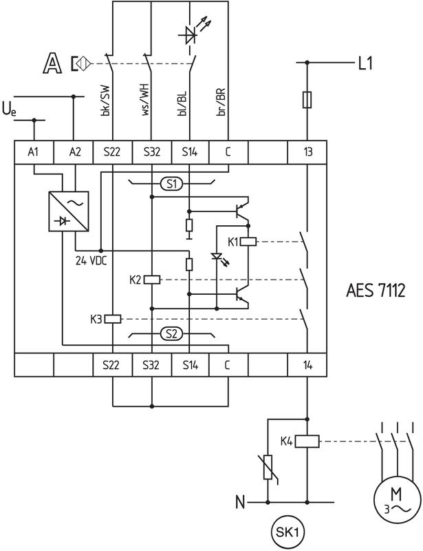
Circuit example
| Note (Wiring diagram) | The wiring diagram is shown with guard doors closed and in de-energised condition. Monitoring 1 guard door(s), each with a magnetic safety sensor of the BNS range Monitoring further guard doors: Further magnetic safety sensors can be connected to S2 in a similar way to those on S1. To secure a guard door up to PL c and Category 1 |
Наш менеджер свяжется с вами в ближайшее время