Работаем с юридическими лицами, бюджетными организациями, ИП
По вопросам приобретения товара пишите на zakaz@lanfor.ru
- Monitoring of BNS range magnetic safety sensors
- 1 safety contact, STOP 0
- 2 Signalling outputs
Ordering data
| Note (Delivery capacity) | Phased-out product |
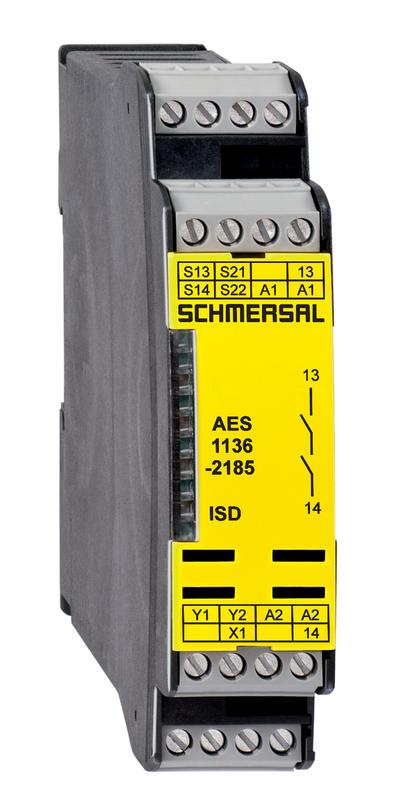
| Product type description | AES 1136-2185 |
| Article number (order number) | 101172221 |
| EAN (European Article Number) | 4030661300450 |
| eCl@ss number, Version 9.0 | 27-37-18-19 |
| eCl@ss number, Version 11.0 | 27-37-18-19 |
| ETIM number, version 6.0 | EC001449 |
| Available until | 31.12.2021 |
Approval - Standards
| Certificates | cULus EAC |
General data
| Standards | IEC/EN 60204-1 IEC 60947-5-3 BG-GS-ET-14 BG-GS-ET-20 EN ISO 13849-1 |
| Climatic stress | EN 60068-2-3 BG-GS-ET-14 |
| Enclosure material | Glass-fibre reinforced thermoplastic, ventilated |
| Material of the contacts, electrical | Ag-Ni 10 and 0.2 µm gold-plated |
| Gross weight | 190 g |
General data - Features
| Stop-Category | 0 |
| Wire breakage detection | Yes |
| Short-circuit recognition | Yes |
| Automatic reset function | Yes |
| Start-up test | Yes |
| Earth connection detection | Yes |
| Integral System Diagnostics, status | Yes |
| Number of LEDs | 1 |
| Number of openers | 2 |
| Number of shutters | 1 |
| Number of undelayed semi-conductor outputs with signaling function | 2 |
| Number of safety contacts | 1 |
| Number of signalling outputs | 2 |
Safety appraisal
| Standards | EN ISO 13849-1 IEC 61508 |
Safety appraisal - Relay outputs
| Performance Level, up to | d |
| Control category to EN13849 | 3 |
| PFH-value | 1.00 x 10⁻⁷ /h |
| Safety Integrity Level (SIL), suitable for applications in | 2 |
| Mission time | 20 Year(s) |
Mechanical data
| Mechanical life, minimum | 20,000,000 Operations |
| Mounting | Snaps onto standard DIN rail to EN 60715 |
Mechanical data - Connection technique
| Terminal Connector | Screw connection rigid or flexible |
| Terminal designations | IEC/EN 60947-1 |
| Cable section, minimum | 0.25 mm² |
| Cable section, maximum | 2.5 mm² |
| Tightening torque of Clips | 0.6 Nm |
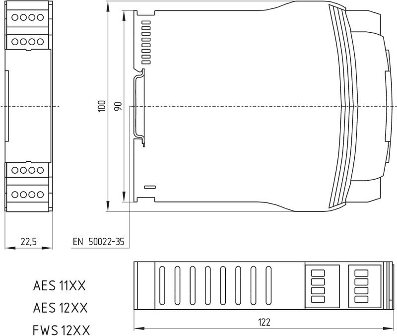
Mechanical data - Dimensions
| Width | 22.5 mm |
| Height | 100 mm |
| Depth | 121 mm |
Ambient conditions
| Degree of protection of the enclosure | IP40 |
| Degree of protection of the mounting space | IP54 |
| Degree of protection of clips or terminals | IP20 |
| Ambient temperature, minimum | +0 °C |
| Ambient temperature, maximum | +55 °C |
| Storage and transport temperature, minimum | -25 °C |
| Storage and transport temperature, maximum | +70 °C |
| Resistance to vibrations to EN 60068-2-6 | 10...55 Hz, Amplitude 0.35 mm, ± 15 % |
| Restistance to shock | 30 g / 11 ms |
Ambient conditions - Insulation value
| Rated impulse withstand voltage Uimp | 4 kV |
| Overvoltage category | III |
| Degree of pollution to IEC/EN 60664-1 | 2 |
Electrical data
| Frequency range | 50 Hz 60 Hz |
| Thermal test current | 6 A |
| Rated operating voltage | 24 VAC -15% / +10% 24 VDC -10%/+20%, residual ripple max. 10% |
| Rated AC voltage for controls, 50 Hz, minimum | 20.4 VAC |
| Rated control voltage at AC 50 Hz, maximum | 26.4 VAC |
| Rated AC voltage for controls, 60 Hz, minimum | 20.4 VAC |
| Rated control voltage at AC 60 Hz, maximum | 26.4 VAC |
| Rated AC voltage for controls at DC minimum | 20.4 VDC |
| Rated control voltage at DC, maximum | 28.8 VDC |
| Electrical power consumption | 5 W |
| Contact resistance, maximum | 0.1 Ω |
| Note (Contact resistance) | in new state |
| Drop-out delay in case of power failure, typically | 80 ms |
| Drop-out delay in case of emergency, typically | 20 ms |
| Pull-in delay at automatic start, maximum, typically | 100 ms |
| Pull-in delay at RESET, typically | 20 ms |
Electrical data - Safe relay outputs
| Voltage, Utilisation category AC15 | 230 VAC |
| Current, Utilisation category AC-15 | 6 A |
| Voltage, Utilisation category DC13 | 24 VDC |
| Current, Utilisation category DC13 | 6 A |
| Switching capacity, minimum | 10 VDC |
| Switching capacity, minimum | 10 mA |
| Switching capacity, maximum | 250 VAC |
| Switching capacity, maximum | 8 A |
Electrical data - Digital inputs
| Input signal, HIGH Signal 1 | 10 … 30 VDC |
| Input signal, LOW Signal 0 | 0 … 2 VDC |
| Conduction resistance, maximum | 40 Ω |
Electrical data - Digital Output
| Voltage, Utilisation category DC12 | 24 VDC |
| Current, Utilisation category DC12 | 0.1 A |
Electrical data - Relay outputs (auxiliary contacts)
| Switching capacity, maximum | 24 VDC |
| Switching capacity, maximum | 2 A |
Electrical data - Electromagnetic compatibility (EMC)
| EMC rating | EMC-Directive |
Integral system diagnosis (ISD)
| Note (ISD -Faults) | The following faults are registered by the safety monitoring modules and indicated by ISD. |
| Faults | Failure of the safety relay to pull-in or drop-out Failure of door contacts to open or close Cross-wire or short-circuit monitoring of the switch connections Interruption of the switch connections Fault on the input circuits or the relay control circuits of the safety monitoring module |
Other data
| Note (applications) | Safety sensor Guard system |
Notes
| Note (General) | Inductive loads (e.g. contactors, relays, etc.) are to be suppressed by means of a suitable circuit. |
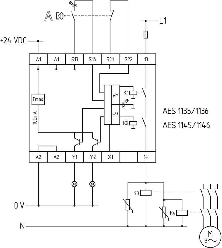
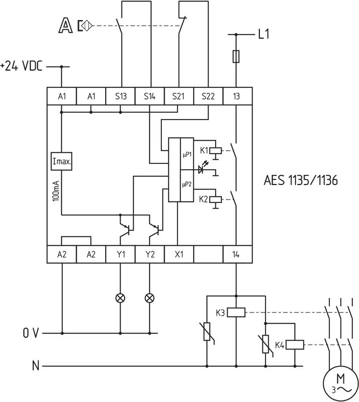
Circuit example
| Note (Wiring diagram) | The wiring diagram is shown with guard doors closed and in de-energised condition. To secure a guard door up to PL d and Category 3 Monitoring 1 guard door(s), each with a magnetic safety sensor of the BNS range If one or two external relays or contactors are used to switch the load, the system can then only be classified in Category 3 to EN ISO 13849-1, if exclusion of the fault “Failure of the external contactors” can be substantiated and is documented, e.g. by using reliable down-rated contactors. A second contactor leads to an increase in the level of security by redundant switching to switch the load off. Modification for 2 NC contacts: The safety monitoring module can be modified to monitor two NC contacts by bridging the terminals A1 and X1. In this configuration, the short-circuit detection becomes inoperative. Expansion of enable delay time: The enable delay time can be increased from 0.1 s to 1.0 s by changing the position of a jumper link connection under the cover of the unit. The ISD tables (Intergral System Diagnostics) for analysis of the fault indications and their causes are shown in the appendix. |
Наш менеджер свяжется с вами в ближайшее время