Работаем с юридическими лицами, бюджетными организациями, ИП
По вопросам приобретения товара пишите на zakaz@lanfor.ru
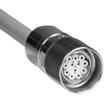
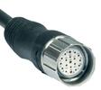
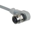
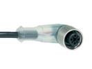
- 1 x connector plug M12, 8-pole
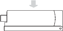
- Actuation from side
- with On-site acknowledgment
- NOTICE: Not available! (Replacement: RSS 36 I)
- Thermoplastic enclosure
- Electronic contact-free, coded system
- Tampering protection by paired coding of sensor and actuator
- Misaligned actuation possible
- High repeat accuracy of the switching points
- Max. length of the sensor chain 200 m
- 2 short-circuit proof PNP safety outputs
- Integral cross-short, wire-breakage and external voltage monitoring of the safety cables up to the control cabinet
Ordering data
| Note (Delivery capacity) | Not available! |
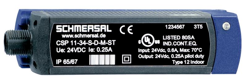
| Product type description | CSP 11-34F2-D-M-ST |
| Article number (order number) | 101208005 |
| EAN (European Article Number) | 4030661382029 |
| eCl@ss number, Version 9.0 | 27-27-24-03 |
| eCl@ss number, Version 11.0 | 27-27-24-03 |
Approval - Standards
| Certificates | cULus EAC |
General data
| Standards | IEC 61508 IEC 60947-5-3 EN ISO 13849-1 |
| Active principle | inductive |
| Housing construction form | Block |
| Installation conditions (mechanical) | not flush |
| Sensor topology | Sensor for series wiring |
| Enclosure material | Glass-fibre, reinforced thermoplastic |
| Active area | Glass-fibre, reinforced thermoplastic |
| Gross weight | 140.5 g |
| Reaction time, maximum | 30 ms |
| Duration of risk, maximum | 60 ms |
General data - Features
| Diagnostic output | Yes |
| Short circuit detection | Yes |
| Short-circuit recognition | Yes |
| Safety functions | Yes |
| Cascadable | Yes |
| Input for reset pushbutton, with edge monitoring | Yes |
| Input for enabling pushbutton, suitable for automatic start | Yes |
| On-site acknowledgment | Yes |
| Integral System Diagnostics, status | Yes |
| Number of LEDs | 3 |
| Number of semi-conductor outputs with signaling function | 1 |
| Number of fail-safe digital outputs | 2 |
| Number of Series-wiring of sensors | 31 |
Safety appraisal
| Standards | IEC 60947-5-3 IEC 61508 | |
| Performance level, up to | e | |
| Control category to EN13849 | 4 | |
| PFH-value | 3.60 x 10⁻⁹ /h | |
| 3 | |
| Mission Time | 20 Year(s) |
Mechanical data
| Actuating panels | lateral |
| Active area | lateral |
| Hysteresis (Switch distance), maximum | 1.5 mm |
| Repeat accuracy R R | 0.5 mm |
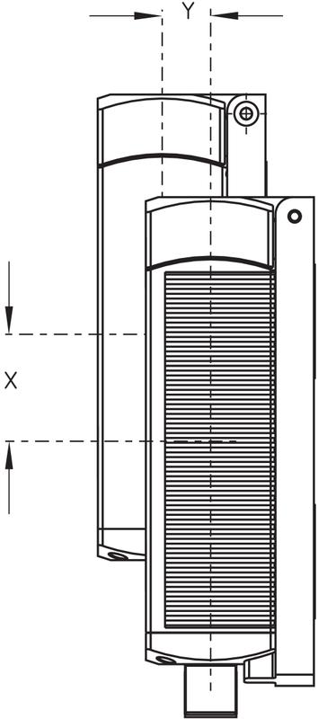
| Note (Repeat accuracy R) | Axial offset: The long side allows for a maximum height misalignment (x) of sensor and actuator of 30 mm (e.g. mounting tolerance or due to guard door sagging). The axial misalignment (y) is max. ± 8 mm. |
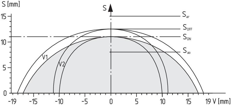
Mechanical data - Switching distances according IEC 60947-5-3
| Switch distance | 11 mm |
| Ensured switch distance ON Sao | 8 mm |
| Ensured switch distance OFF Sar | 15 mm |
Mechanical data - Connection technique
| Terminal Connector | Connector plug M12, 8-pole |
| Note | The cable section of the interconnecting cable must be observed for both wiring variants! Cable length and cable section alter the voltage drop depending on the output current |
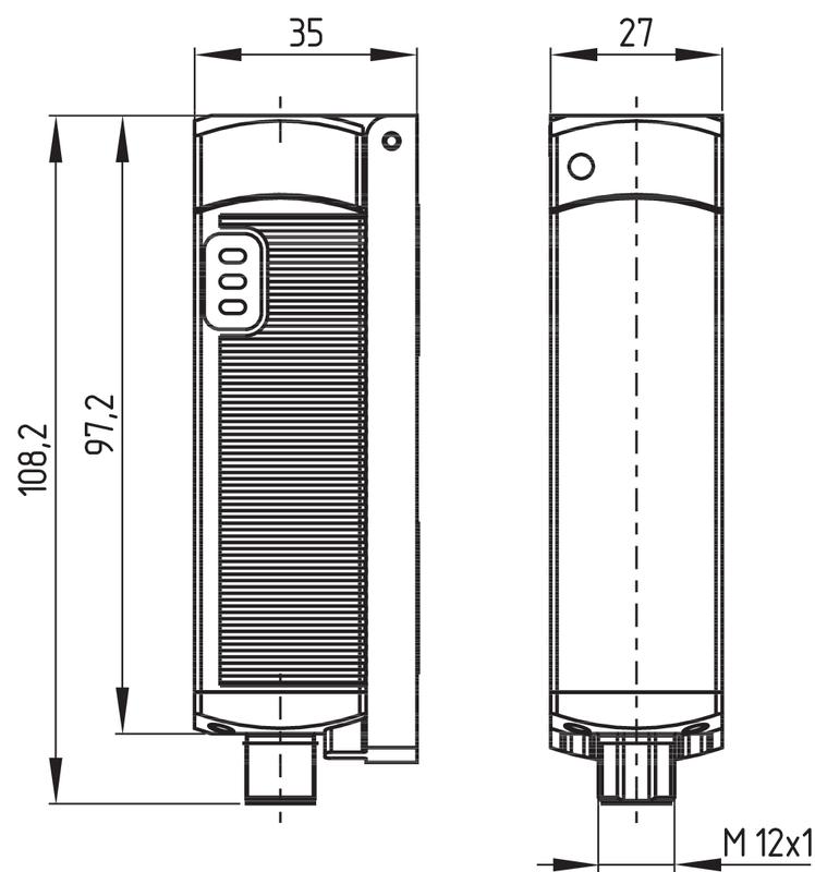
Mechanical data - Dimensions
| Length of sensor | 27 mm |
| Width of sensor | 35 mm |
| Height of sensor | 108.2 mm |
Ambient conditions
| Degree of protection | IP65 to EN 60529 IP67 to EN 60529 |
| Ambient temperature, minimum | -25 °C |
| Ambient temperature, maximum | +70 °C |
| Storage and transport temperature, minimum | -25 °C |
| Storage and transport temperature, maximum | +85 °C |
| Resistance to vibrations to EN 60068-2-6 | 10 … 55 Hz, amplitude 1 mm |
| Restistance to shock | 30 g / 11 ms |
| Protection rating | II |
Ambient conditions - Insulation value
| Rated insulation voltage Ui | 32 VAC/DC |
| Rated impulse withstand voltage Uimp | 0.8 kV |
| Overvoltage category | III |
| Degree of pollution to VDE 0100 | 3 |
Electrical data
| Voltage type | DC (direct current) |
| No-load supply current I0 | 100 mA |
| Rated operating voltage, minimum | 20.4 VDC |
| Rated operating voltage, maximum | 26.4 VDC |
| Operating current | 600 mA |
| Required rated short-circuit current to EN 60947-5-1 | 100 A |
| Utilisation category DC-12 | 24 VDC |
| Utilisation category DC-12 | 0.05 A |
| Utilisation category DC-13 | 24 VDC |
| Utilisation category DC-13 | 0.05 A |
| Switching frequency, approx. | 3 Hz |
Electrical data - Fail-safe digital outputs
| Rated operating current (safety outputs) | 250 mA |
| Output current, (fail-safe output), maximum | 0.25 A |
| Versions | p-type |
| Voltage drop Ud, maximum | 0.5 V |
| Current leakage Ir | 0.5 mA |
| Voltage, Utilisation category DC12 | 24 VDC |
| Current, Utilisation category DC12 | 0.25 A |
| Voltage, Utilisation category DC13 | 24 VDC |
Electrical data - Digital Output
| Versions | p-type |
Electrical data - Diagnostic output
| Operating current | 50 mA |
| Voltage drop Ud, maximum | 5 V |
| Voltage, Utilisation category DC12 | 24 VDC |
Electrical data - Electromagnetic compatibility (EMC)
| Interfering radiation | IEC 61000-6-4 |
| EMC rating | IEC 61000-6-2 |
Pin assignment
| PIN 1 | 1A1 Ue: (1) |
| PIN 2 | X1 Safety input 1 |
| PIN 3 | A2 GND |
| PIN 4 | Y1 Safety output 1 |
| PIN 5 | OUT Diagnostic output OUT |
| PIN 6 | X2 Safety input 2 |
| PIN 7 | Y2 Safety output 2 |
| PIN 8 | IN On-site acknowledgment |
Scope of delivery
| Included in delivery | Actuators must be ordered separately. |
Accessory
| Recommendation (actuator) | CSP 34-S-1 |
| Recommended safety switchgear | PROTECT PSC1 SRB-E-301ST SRB-E-201LC |
Notes
| Note (General) | When safety gate monitoring by the safety sensor CSP 34F2 is required, an acknowledge button should be positioned so that the danger area can be viewed. When the button is pushed, a 24 VDC signal is generated at the reset input of the CSP 34F2. If the gate is closed the safety outputs are released with the negative signal edge. After the gate is opened it needs to be acknowledge before it can be released again. On-site acknowledgment |
Наш менеджер свяжется с вами в ближайшее время