
Работаем с юридическими лицами, бюджетными организациями, ИП
По вопросам приобретения товара пишите на zakaz@lanfor.ru
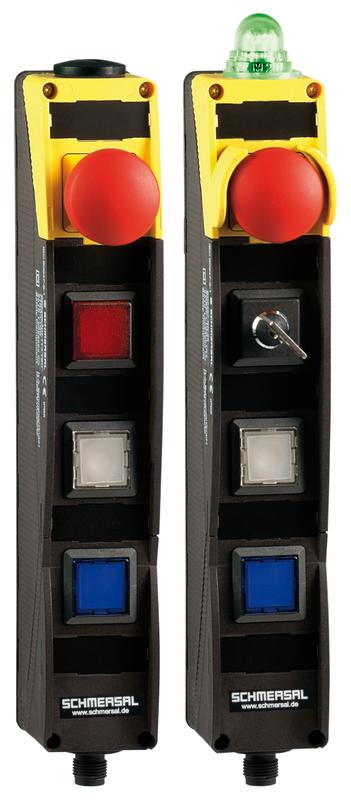
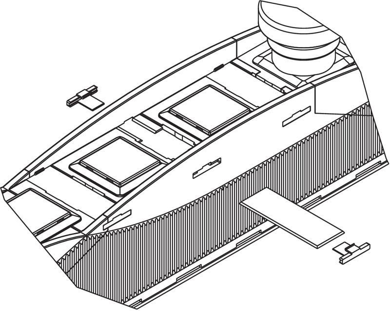
- Pos 1: E-STOP with protective collar
- Pos 2: RED signal light
- Pos 3: WHITE illuminated pushbutton
- Pos 4: BLUE illuminated pushbutton
- Integrated AS-Interface
- with connector plug M12 bottom
- slender shock-proof thermoplastic enclosure
- to be installed at an ergonomic favourable position
- to be fitted to commercial-off-the-shelf aluminium profiles
Ordering data
| Product type description | BDF200-ST1-AS-NHK-LMRD-LTWH-LTBU |
| Article number (order number) | 101215387 |
| EAN (European Article Number) | 4030661448459 |
| eCl@ss number, Version 9.0 | 27-33-02-04 |
| eCl@ss number, Version 11.0 | 27-33-02-04 |
| ETIM number, version 6.0 | EC001415 |
Approval - Standards
| Certificates | TÜV cULus ASi-SaW EAC |
General data
| Standards | IEC 61508 EN 60947-5-1 EN ISO 13850 EN 62026-2 EN ISO 13849-1 |
| Climatic stress | DIN EN 60068 |
| Enclosure material | Plastic, glass-fibre reinforced thermoplastic, self-extinguishing |
| Gross weight | 280 g |
| Reaction time, maximum | 100 ms |
| Positions used, position 1 | Emergency stop, with protective collar |
| Positions used, position 2 | Illuminated signal, red |
| Positions used, position 3 | Illuminated pushbutton, white |
| Positions used, position 4 | Illuminated pushbutton, blue |
General data - Features
| Indicator lamp | No |
Safety appraisal
| Standards | IEC 61508 | |
| Performance level, up to | e | |
| Control category to EN13849 | 4 | |
| PFH-value | 1.40 x 10⁻⁸ /h | |
| Note (PFH-value) | up to max. 5,000 switching cycles/year | |
| 3 | |
| Mission Time | 20 Year(s) |
Mechanical data
| Mechanical life, Emergency-Stop button | 100,000 Operations |
| Mechanical life, Command devices | 1,000,000 Operations |
Mechanical data - Connection technique
| Terminal Connector | Connector plug M12, 4-pole, (A-coding) |
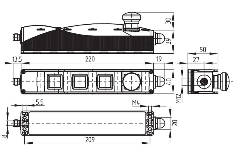
Mechanical data - Dimensions
| Width | 40 mm |
| Height | 69 mm |
| Depth | 233.5 mm |
Ambient conditions
| Degree of protection | IP65 |
| Ambient temperature, minimum | -25 °C |
| Ambient temperature, maximum | +65 °C |
| Storage and transport temperature, minimum | -25 °C |
| Storage and transport temperature, maximum | +85 °C |
| Resistance to vibrations to EN 60068-2-6 | 10 … 150 Hz, amplitude 0.35 mm / 5 g |
| Restistance to shock | 15 g / 11 ms |
| Protection rating | II |
Ambient conditions - Insulation value
| Rated insulation voltage Ui | 32 VDC |
| Rated impulse withstand voltage Uimp | 0.8 kV |
| Overvoltage category | III |
| Degree of pollution to IEC/EN 60664-1 | 3 |
Electrical data - AS Interface
| AS-i Operating voltage, minimum | 18 VDC |
| AS-i Operating voltage AS-i maximum | 31.6 VDC |
| Note (AS-i Operating voltage) | Protection against polarity reversal |
| AS-i Current consumption, maximum | 150 mA |
Electrical data - AS-Interface specification
| Note (AS-i Parameter bits) | Set the parameter outputs to '1111' (0xF) FID: periphery error |
| AS-i Version (Safety-Slave) | V 3.0 |
| AS-i Profile (Safety-Slave) | S-7.B.F.F |
| AS-i Input, Channel 1 (Safety-Slave) | Data bits DI 0 / DI 1 = dynamic code transmission |
| AS-i Input, Channel 2 (Safety-Slave) | Data bits DI 2 / DI 3 = dynamic code transmission |
| AS-i Output, DO 0 (Safety-Slave) | Indicator lamp G24 red |
| AS-i Output, DO 1 (Safety-Slave) | Indicator lamp G24 green |
| AS-i Output, DO 2 (Safety-Slave) | No Function |
| AS-i Output, DO 3 (Safety-Slave) | No Function |
| AS-i AS-i Parameter bits (Safety-Slave), P0 ... P3 | No function |
| AS-i Version (A/B Slave) | V 3.0 |
| AS-i Profile (A/B Slave) | S-7.A.7.F |
| AS-i Input, DI 0 (A/B Slave) | Command device Position 4 |
| AS-i Input, DI 1 (A/B Slave) | Command device Position 3 |
| AS-i Input, DI 2 (A/B Slave) | Command device Position 2 |
| AS-i Input, DI 3 (A/B Slave) | Command device Position 2 |
| AS-i Output, DO 0 (A/B Slave) | Illuminated signal position 4 |
| AS-i Output, DO 2 (A/B Slave) | Illuminated signal position 2 |
| AS-i Output, DO 1 (A/B Slave) | Illuminated signal position 3 |
| AS-i Output, DO 3 (A/B Slave) | No Function |
| AS-i AS-i Parameter bits (A/B Slave), P0 ... P3 | No function |
| AS-i Input module address | 0 |
| Note (AS-i Input module address) | Preset to address 0, can be changed through AS-interface bus master or hand-held programming device |
| Note | Both AS-i slaves can be enabled and disabled through the integrated DIP switch. The addressing must take place via the M12 connector. |
Pin assignment
| PIN 1 | AS-Interface + |
| PIN 2 | n.c. |
| PIN 3 | AS-Interface - |
| PIN 4 | n.c. |
Наш менеджер свяжется с вами в ближайшее время