Работаем с юридическими лицами, бюджетными организациями, ИП
По вопросам приобретения товара пишите на zakaz@lanfor.ru
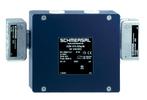
- Can be used for CSS and RSS sensors, as well as for MZM 100, AZM 201, AZM 300, AZM40
- Safe active AS-i distributor
- Connections for profile cable AS-i & AUX
- With 2 fail-safe inputs for OSSDs and one digital output that is not fail-safe
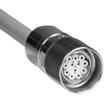
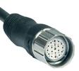
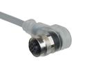
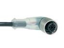
- M12, 8-pole connecting cable 1 m
- Protection class IP67
Ordering data
| Product type description | BWU3635 |
| Article number (order number) | 103016678 |
| EAN (European Article Number) | 4030661508924 |
| eCl@ss number, Version 9.0 | 27-24-26-04 |
| eCl@ss number, Version 11.0 | 27-24-26-04 |
| ETIM number, version 6.0 | EC001599 |
General data
| Standards | EN 62061 EN 62026-2 EN ISO 13849-1 |
| Enclosure material | Plastic |
| Gross weight | 141.3 g |
| Reaction time, maximum | 11 ms |
General data - Features
| Safety functions | Yes |
| Integral System Diagnostics, status | Yes |
Safety appraisal
| Standards | EN 62061 | |
| Performance level, up to | e | |
| Control category to EN13849 | 4 | |
| PFH-value | 5.18 x 10⁻⁹ /h | |
| PFD value | 6.19 x 10⁻⁷ | |
| 3 | |
| Mission Time | 20 Year(s) |
Mechanical data - Connection technique
| Terminal Connector | Cable connector M12, 8-pole, A-coded |
| Length of cable | 1 m |
| Material of the cable | PUR |
Mechanical data - Dimensions
| Width | 60 mm |
| Height | 45 mm |
| Depth | 19 mm |
Ambient conditions
| Degree of protection | IP67 |
| Ambient temperature, minimum | -20 °C |
| Ambient temperature, maximum | +60 °C |
| Storage and transport temperature, minimum | -30 °C |
| Storage and transport temperature, maximum | +85 °C |
| Resistance to vibrations to EN 60068-2-6 | 10 … 55 Hz, amplitude 0.5 mm |
| Restistance to shock | 15 g / 11 ms |
Electrical data - AS Interface
| AS-i Operating voltage, minimum | 21.6 VDC |
| AS-i Operating voltage AS-i maximum | 31.6 VDC |
| AS-i Current consumption, maximum | 60 mA |
Electrical data - AS-Interface specification
| AS-i Specification | Safety-Slave |
| AS-i Version | V 2.1 |
| AS-i Profile | S-7.B.F.1 |
| AS-i Input, Channel 1 | Data bits DI 0 / DI 1 = dynamic code transmission |
| AS-i Input, Channel 2 | Data bits DI 2 / DI 3 = dynamic code transmission |
| AS-i Outputs, DO 0 | Digital output, Solenoid control |
| AS-i Outputs, DO 1 … DO 3 | No Function |
| AS-i Parameter bits, P0 | Control system watchdog |
| AS-i Parameter bits, P1 | Diagnostics signal safety switchgear (inverted) |
| AS-i Parameter bits, P2 ... P3 | No function |
| Note (AS-i Parameter bits) | Set the parameter outputs to '1111' (0xF) |
| AS-i Input module address | 0 |
| Note (AS-i Input module address) | Preset to address 0, can be changed through AS-interface bus master or hand-held programming device |
Electrical data - Auxiliary voltage
| Rated operating voltage | 24 VDC -15% / +10% (stabilised PELV) |
Status indication
| Note (LED switching conditions display) | (1) green/red LED (AS-i duo LED): Supply voltage / communication error / slave address = 0 / periphery error detected (2) LED green: AUX-Power available (3) LED yellow: S1 = Status safety input 1 (4) LED yellow: S2 = Status safety input 2 (5) LED yellow: I1 = Status input I1 (6) LED yellow: o1 = Status output o1 |
Наш менеджер свяжется с вами в ближайшее время