Работаем с юридическими лицами, бюджетными организациями, ИП
По вопросам приобретения товара пишите на zakaz@lanfor.ru
- Universal coding with RFID technology
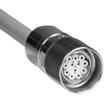
- 1 x connector socket M12, 8-pole
- Actuation from side
- Max. 31 sensors can be wired in series.
- serial diagnostic output
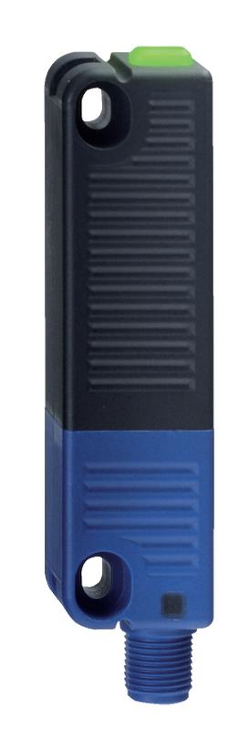
- Thermoplastic enclosure
- RFID-technology for needs-based protection against tampering
- Misaligned actuation possible
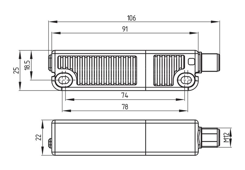
- 27 mm x 108.2 mm x 35 mm
- High repeat accuracy of the switching points
- 2 short-circuit proof PNP safety outputs
- Integral cross-short, wire-breakage and external voltage monitoring of the safety cables up to the control cabinet
Ordering data
| Product type description | RSS 36-SD-ST |
| Article number (order number) | 101214772 |
| EAN (European Article Number) | 4030661413402 |
| eCl@ss number, Version 9.0 | 27-27-24-03 |
| eCl@ss number, Version 11.0 | 27-27-24-03 |
Approval - Standards
| Certificates | TÜV cULus ECOLAB EAC FCC IC |
General data
| Standards | IEC 60947-5-3 |
| general information | Universal coding |
| Coding level according to ISO 14119 | Low |
| Active principle | RFID |
| Housing construction form | Block |
| Installation conditions (mechanical) | not flush |
| Sensor topology | Sensor for series wiring |
| Enclosure material | Plastic, glass-fibre reinforced thermoplastic, self-extinguishing |
| Active area | Glass-fibre, reinforced thermoplastic |
| Gross weight | 85 g |
| Time to readiness, maximum | 2,000 ms |
| Reaction time, maximum | 100 ms |
| Duration of risk, maximum | 200 ms |
General data - Features
| Serial diagnostics | Yes |
| Diagnostic output | Yes |
| Short circuit detection | Yes |
| Short-circuit recognition | Yes |
| Safety functions | Yes |
| Cascadable | Yes |
| Integral System Diagnostics, status | Yes |
| Number of LEDs | 3 |
| Number of semi-conductor outputs with signaling function | 1 |
| Number of fail-safe digital outputs | 2 |
| Number of Series-wiring of sensors | 31 |
Safety appraisal
| Standards | EN ISO 13849-1 IEC 60947-5-3 EN 62061 IEC 61508 | |
| Performance level, up to | e | |
| Control category to EN13849 | 4 | |
| PFH-value | 2.70 x 10⁻¹⁰ /h | |
| 3 | |
| Mission Time | 20 Year(s) |
Mechanical data
| Actuating panels | lateral |
| Active area | lateral |
| Hysteresis (Switch distance), maximum | 2 mm |
| Repeat accuracy R R | 0.5 mm |
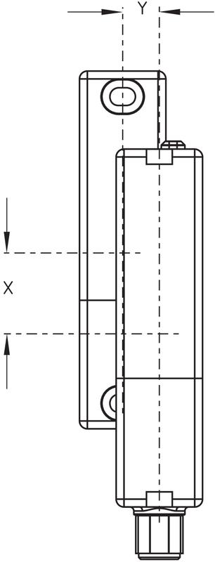
| Note (Repeat accuracy R) | Axial offset: The long side allows for a maximum height misalignment (x) of sensor and actuator of 8 mm (e.g. mounting tolerance or due to guard door sagging). The axial misalignment (y) is max. ± 18 mm (see figure: Operating principle). Minimum clearance between two sensor systems 100 mm. |
| Mounting | A screw length of 25 mm is sufficient for sensor mounting and for side mounting of the actuators. 30 mm long screws are recommended when the actuator is mounted upright and/or when the sealing discs are used. |
Mechanical data - Switching distances according IEC 60947-5-3
| Switch distance | 12 mm |
| Ensured switch distance ON Sao | 10 mm |
| Ensured switch distance OFF Sar | 20 mm |
Mechanical data - Connection technique
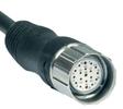
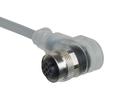
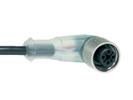
| Terminal Connector | Connector M12, 8-pole |
| Note | The cable section of the interconnecting cable must be observed! Cable length and cable section alter the voltage drop depending on the output current |
Mechanical data - Dimensions
| Length of sensor | 22 mm |
| Width of sensor | 106.3 mm |
| Height of sensor | 25 mm |
Ambient conditions
| Degree of protection | IP65 to EN 60529 IP67 to EN 60529 IP69 to EN 60529 |
| Ambient temperature, minimum | -25 °C |
| Ambient temperature, maximum | +70 °C |
| Storage and transport temperature, minimum | -25 °C |
| Storage and transport temperature, maximum | +85 °C |
| Material temperature resistance of the cable (in motion), minimum | -10 °C |
| Material temperature resistance of the cable (at rest), minimum | -30 °C |
| Material temperature resistance (long-term), maximum | +105 °C |
| Resistance to vibrations to EN 60068-2-6 | 10 … 55 Hz, amplitude 1 mm |
| Restistance to shock | 30 g / 11 ms |
| Protection rating | III |
Ambient conditions - Insulation value
| Rated insulation voltage Ui | 32 VDC |
| Rated impulse withstand voltage Uimp | 0.8 kV |
| Overvoltage category | III |
| Degree of pollution to VDE 0100 | 3 |
Electrical data
| Voltage type | DC (direct current) |
| No-load supply current I0 | 100 mA |
| Rated operating voltage | 24 VDC −15 % / +10 % |
| Rated operating voltage, minimum | 20.4 VDC |
| Rated operating voltage, maximum | 26.4 VDC |
| Operating current | 600 mA |
| Required rated short-circuit current to EN 60947-5-1 | 100 A |
| Switching frequency, approx. | 1 Hz |
Electrical data - Fail-safe digital outputs
| Rated operating current (safety outputs) | 250 mA |
| Output current, (fail-safe output), maximum | 0.25 A |
| Versions | p-type |
| Voltage drop Ud, maximum | 1 V |
| Current leakage Ir | 0.5 mA |
| Voltage, Utilisation category DC12 | 24 VDC |
| Current, Utilisation category DC12 | 0.25 A |
| Voltage, Utilisation category DC13 | 24 VDC |
| Current, Utilisation category DC13 | 0.25 A |
Electrical data - Diagnostic output
| Operating current | 150 mA |
| Versions | p-type |
| Voltage drop Ud, maximum | 2 V |
Electrical data - Electromagnetic compatibility (EMC)
| Interfering radiation | IEC 61000-6-4 |
| EMC rating | IEC 60947-3 |
Status indication
| Note (LED switching conditions display) | LED yellow: Operating condition LED green: Supply voltage LED red: Fault |
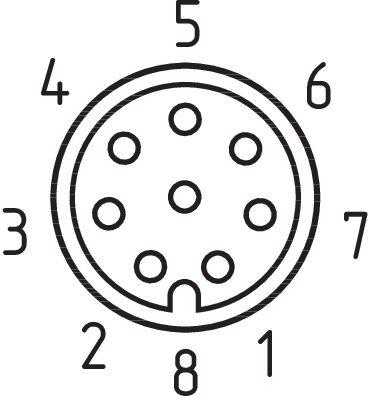
Pin assignment
| PIN 1 | A1 Ue Brown |
| PIN 2 | X1 Safety input 1 White |
| PIN 3 | A2 GND Blue |
| PIN 4 | Y1 Safety output 1 Black |
| PIN 5 | serial diagnostic output OUT Grey |
| PIN 6 | X2 Safety input 2 violet |
| PIN 7 | Y2 Safety output 2 red |
| PIN 8 | IN serial diagnostic input Pink |
Scope of delivery
| Included in delivery | Actuators must be ordered separately. |
Accessory
| Recommendation (actuator) | RST 36-1 RST 36-1-R |
| Recommended safety switchgear | PROTECT PSC1 SRB-E-301ST SRB-E-201LC |
Notes
| Note (General) | Evaluation requirements: dual-channel safety input, suitable for p-type sensors with NO function. The safety-monitoring module must tolerate internal functional tests of the sensors with cyclic switch-off of the sensor outputs for max. 2 ms. Short-circuit recognition by the evaluation is not necessary. |
Наш менеджер свяжется с вами в ближайшее время