Работаем с юридическими лицами, бюджетными организациями, ИП
По вопросам приобретения товара пишите на zakaz@lanfor.ru
- Fail-safe standstill monitors
- Sensor-free detection of standstill by monitoring e.m.f.
- Direct connection to three-phase motors
- Suitable for connection to a frequency converter with the following interface date: rotary hysteresis 0 ... 1000 Hz, switching frequency of the end level up to 16 kHz, engine voltage range 0 ... 400 V
- This fail-safe standstill monitor has the particular advantage that no adjustment for a required-value is needed during comissioning.
- 3 safety contacts, STOP 0
- 1 Signalling output
Ordering data
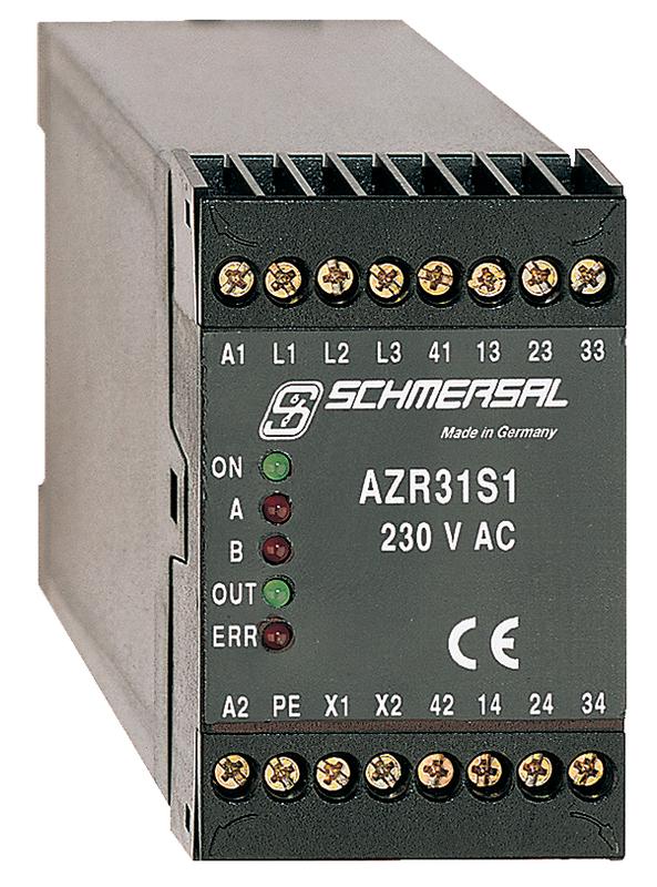
| Product type description | AZR31S1/230VAC |
| Article number (order number) | 101049665 |
| EAN (European Article Number) | 4250116202539 |
| eCl@ss number, Version 9.0 | 27-37-18-19 |
| eCl@ss number, Version 11.0 | 27-37-18-19 |
| ETIM number, version 6.0 | EC001449 |
Approval - Standards
| Certificates | EAC |
General data
| Standards | IEC 61508 IEC/EN 60204-1 EN 60947-5-1 EN ISO 13849-1 |
| Climatic stress | EN 60068-2-78 |
| Enclosure material | Glass-fibre, reinforced thermoplastic |
| Material of the contacts, electrical | AgSn0. self-cleaning, positive drive |
| Gross weight | 480 g |
General data - Features
| Stop-Category | 0 |
| Wire breakage detection | Yes |
| Short-circuit recognition | Yes |
| Feedback circuit | Yes |
| Automatic reset function | Yes |
| Earth connection detection | Yes |
| Integral System Diagnostics, status | Yes |
| Number of auxiliary contacts | 1 |
| Number of LEDs | 5 |
| Number of safety contacts | 3 |
Safety appraisal
| Standards | EN 60947-5-1 IEC 61508 |
| PFH-value | 2.00 x 10⁻⁸ /h |
| Mission Time | 20 Year(s) |
| Common Cause Failure (CCF), minimum | 65 |
Safety appraisal - Relay outputs
| Performance level, stop 0, up to | e |
| Category, Stop 0 | 4 |
| Diagnostic Coverage (DC) Level, Stop 0 | ≥ 99 % |
| Safety Integrity Level (SIL), Stop 0, suitable for applications in | 3 |
Mechanical data
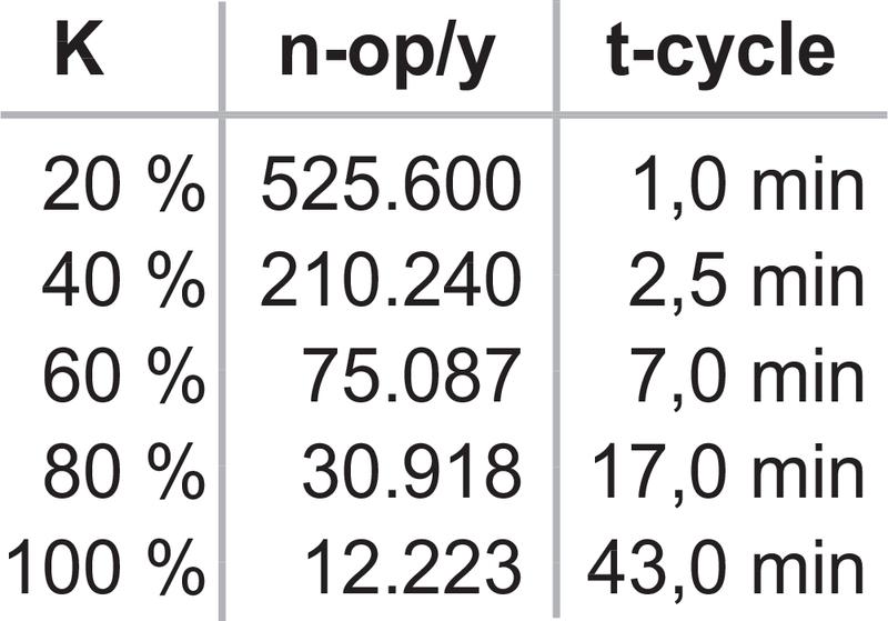
| Mechanical life, minimum | 10,000,000 Operations |
| Mounting | Snaps onto standard DIN rail to EN 60715 |
Mechanical data - Connection technique
| Terminal Connector | Screw connection rigid or flexible |
| Terminal designations | IEC/EN 60947-1 |
| Cable section, minimum | 0.25 mm² |
| Cable section, maximum | 2.5 mm² |
| Tightening torque of Clips | 0.6 Nm |
Mechanical data - Dimensions
| Width | 45 mm |
| Height | 73.2 mm |
| Depth | 121 mm |
Ambient conditions
| Degree of protection of the enclosure | IP40 |
| Degree of protection of the mounting space | IP54 |
| Degree of protection of clips or terminals | IP20 |
| Ambient temperature, minimum | -25 °C |
| Ambient temperature, maximum | +45 °C |
| Storage and transport temperature, minimum | -40 °C |
| Storage and transport temperature, maximum | +85 °C |
| Resistance to vibrations to EN 60068-2-6 | 10 ... 55 Hz, Amplitude 0.35 mm |
| Restistance to shock | 30 g / 11 ms |
Ambient conditions - Insulation value
| Rated impulse withstand voltage Uimp | 4 kV |
| Overvoltage category | III |
| Degree of pollution to IEC/EN 60664-1 | 2 |
Electrical data
| Frequency range | 50 Hz 60 Hz |
| Rated operating voltage | 230 VAC -15% / +10% |
| Rated AC voltage for controls, 50 Hz, minimum | 195.5 VAC |
| Rated control voltage at AC 50 Hz, maximum | 253 VAC |
| Rated AC voltage for controls, 60 Hz, minimum | 195.5 VAC |
| Rated control voltage at AC 60 Hz, maximum | 253 VAC |
| Electrical power consumption, maximum | 4 VA |
| Contact resistance, maximum | 0.1 Ω |
| Note (Contact resistance) | in new state |
| Cable length (Master/Slave), maximum | 10 m |
| Drop-out delay in case of power failure, typically | 80 ms |
| Drop-out delay in case of emergency, typically | 20 ms |
| Drop-out delay in case of emergency stop, maximum | 15 ms |
| Pull-in delay at automatic start (after detecting standstill), approx. | 7,000 ms |
| Pull-in delay at RESET, typically | 20 ms |
Electrical data - Safe relay outputs
| Voltage, Utilisation category AC15 | 230 VAC |
| Current, Utilisation category AC-15 | 6 A |
| Voltage, Utilisation category DC13 | 24 VDC |
| Current, Utilisation category DC13 | 6 A |
| Switching capacity, minimum | 10 VDC |
| Switching capacity, minimum | 10 mA |
| Switching capacity, maximum | 250 VAC |
| Switching capacity, maximum | 8 A |
Electrical data - Digital inputs
| Conduction resistance, maximum | 40 Ω |
Electrical data - Digital Output
| Voltage, Utilisation category DC12 | 24 VDC |
| Current, Utilisation category DC12 | 0.1 A |
Electrical data - Relay outputs (auxiliary contacts)
| Switching capacity, maximum | 24 VDC |
| Switching capacity, maximum | 2 A |
Electrical data - Electromagnetic compatibility (EMC)
| EMC rating | EMC-Directive |
Status indication
| Indicated operating states | OUT, green: release ON, green: supply voltage UB ERR, red: error channel A + B |
Other data
| Note (applications) | safe standstill monitoring |
Notes
| Note (General) | Inductive loads (e.g. contactors, relays, etc.) are to be suppressed by means of a suitable circuit. |
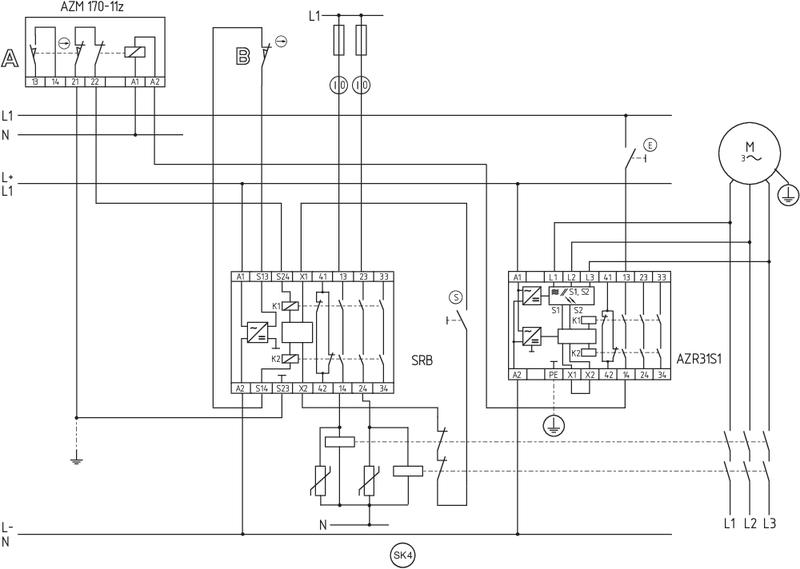
Circuit example
| Note (Wiring diagram) | The wiring diagram is shown with guard doors closed and in de-energised condition. The sensor-free standstill monitor checks the e.m.f. of the three phase motor. The SRB range guard door monitor checks the position of the guard door. Monitoring the guard door using a solenoid interlock and a safety switch with separate actuator (A and B). Release takes place by means of the NO contact (E) only when the run-down movement has been terminated. After release has taken place, the guard door must be opened. To secure a guard door |
Наш менеджер свяжется с вами в ближайшее время