Работаем с юридическими лицами, бюджетными организациями, ИП
По вопросам приобретения товара пишите на zakaz@lanfor.ru
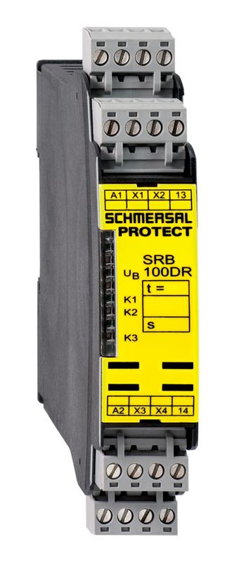
- Safety relay module for double reset
- Suitable for signal processing of potential-free outputs, e.g. command devices
- 1 safety contact, STOP 0
Ordering data
| Product type description | SRB100DR |
| Article number (order number) | 101186279 |
| EAN (European Article Number) | 4250116202218 |
| eCl@ss number, Version 9.0 | 27-37-18-19 |
| eCl@ss number, Version 11.0 | 27-37-18-19 |
| ETIM number, version 6.0 | EC001449 |
General data
| Standards | IEC 61508 IEC/EN 60204-1 EN 60947-5-1 EN ISO 13849-1 |
| Climatic stress | EN 60068-2-78 |
| Enclosure material | Glass-fibre reinforced thermoplastic, ventilated |
| Material of the contacts, electrical | Ag-Ni, self-cleaning, positive drive |
| Gross weight | 250 g |
General data - Features
| Electronic Fuse | Yes |
| Wire breakage detection | Yes |
| Start input | Yes |
| Reset after disconnection of supply voltage | Yes |
| Earth connection detection | Yes |
| Integral System Diagnostics, status | Yes |
| Number of LEDs | 4 |
| Number of openers | 2 |
| Number of safety contacts | 1 |
Safety appraisal
| Standards | EN 60947-5-1 IEC 61508 |
Safety appraisal - Relay outputs
| PFH-Value Stop 0 | 2.00 x 10⁻⁸ /h |
| Mission time | 20 Year(s) |
Mechanical data
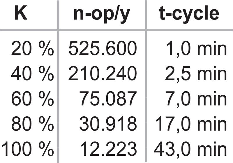
| Mechanical life, minimum | 10,000,000 Operations |
| Mounting | Snaps onto standard DIN rail to EN 60715 |
Mechanical data - Connection technique
| Terminal Connector | Screw connection rigid or flexible |
| Terminal designations | IEC/EN 60947-1 |
| Cable section, minimum | 0.25 mm² |
| Cable section, maximum | 2.5 mm² |
| Tightening torque of Clips | 0.6 Nm |
Mechanical data - Dimensions
| Width | 22.5 mm |
| Height | 100 mm |
| Depth | 121 mm |
Ambient conditions
| Degree of protection of the enclosure | IP40 |
| Degree of protection of the mounting space | IP54 |
| Degree of protection of clips or terminals | IP20 |
| Ambient temperature, minimum | -25 °C |
| Ambient temperature, maximum | +60 °C |
| Storage and transport temperature, minimum | -40 °C |
| Storage and transport temperature, maximum | +85 °C |
| Resistance to vibrations to EN 60068-2-6 | 10...55 Hz, Amplitude 0.35 mm, ± 15 % |
| Restistance to shock | 30 g / 11 ms |
Ambient conditions - Insulation value
| Rated impulse withstand voltage Uimp | 4 kV |
| Overvoltage category | III |
| Degree of pollution to IEC/EN 60664-1 | 2 |
Electrical data
| Frequency range | 50 Hz 60 Hz |
| Rated operating voltage | 24 VAC -15% / +10% 24 VDC -15% / +20%, residual ripple max. 10 % |
| Rated AC voltage for controls, 50 Hz, minimum | 20.4 VAC |
| Rated control voltage at AC 50 Hz, maximum | 26.4 VAC |
| Rated AC voltage for controls, 60 Hz, minimum | 20.4 VAC |
| Rated control voltage at AC 60 Hz, maximum | 26.4 VAC |
| Rated AC voltage for controls at DC minimum | 20.4 VDC |
| Rated control voltage at DC, maximum | 28.8 VDC |
| Electrical power consumption | 3.2 W |
| Electrical power consumption | 6 VA |
| Contact resistance, maximum | 0.1 Ω |
| Note (Contact resistance) | in new state |
| Drop-out delay in case of power failure, typically | 80 ms |
| Drop-out delay in case of emergency, typically | 20 ms |
| Pull-in delay at automatic start, maximum, typically | 100 ms |
| Pull-in delay at RESET, typically | 20 ms |
Electrical data - Safe relay outputs
| Voltage, Utilisation category AC15 | 230 VAC |
| Current, Utilisation category AC-15 | 6 A |
| Voltage, Utilisation category DC13 | 24 VDC |
| Current, Utilisation category DC13 | 6 A |
| Switching capacity, minimum | 10 VDC |
| Switching capacity, minimum | 10 mA |
| Switching capacity, maximum | 250 VAC |
| Switching capacity, maximum | 8 A |
Electrical data - Digital inputs
| Conduction resistance, maximum | 40 Ω |
Electrical data - Relay outputs (auxiliary contacts)
| Switching capacity, maximum | 24 VDC |
| Switching capacity, maximum | 2 A |
Electrical data - Electromagnetic compatibility (EMC)
| EMC rating | EMC-Directive |
Status indication
| Indicated operating states | Position relay K2 Position relay K1 Position relay K3 |
Notes
| Note (General) | Inductive loads (e.g. contactors, relays, etc.) are to be suppressed by means of a suitable circuit. |
Circuit example
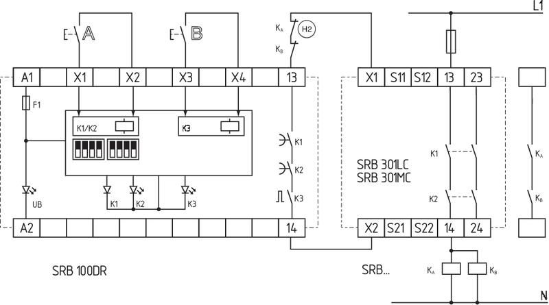
| Note (Wiring diagram) | The wiring diagram is shown with guard doors closed and in de-energised condition. Applications: #Picture#Bilddata/Sonstige/_quitz01.eps#/Picture# safety relay module for double reset Start configuration: 2 time-dependent reset/on switches 1st and 2nd monitoring time between the 1st and 2nd reset button from 3 … 30 seconds adjustable through DIP switches The monitoring time is set through DIP switches located below the cover of the enclosure front. (Factory setting: 3 seconds) Actuator configuration: 1-channel control (output impulse approx. 200 ms) of the reset input of a downstream safety relay module Edge detection: After the device is reset, the trailing edge is evaluated, so that errors, e.g. welded contacts or manipulations cannot lead to dangerous situations. (H2) = Feedback circuit |
Наш менеджер свяжется с вами в ближайшее время