Работаем с юридическими лицами, бюджетными организациями, ИП
По вопросам приобретения товара пишите на zakaz@lanfor.ru
- Reset with trailing edge
- 1 safety contact
- Suitable for signal processing of emergency stop control devices, interlocking equipment, etc
- Installation in Ex-Zone 2
Ordering data
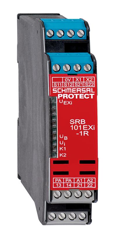
| Product type description | SRB101EXi-1R |
| Article number (order number) | 103037574 |
| EAN (European Article Number) | 4030661542720 |
| eCl@ss number, Version 9.0 | 27-37-18-19 |
| eCl@ss number, Version 11.0 | 27-37-18-19 |
| ETIM number, version 6.0 | EC001449 |
Explosion protection
| Explosion protection: regulations | EN 60079-0 EN 60079-11 EN 60079-15 |
| Explosion protection zones | 1 21 |
| Explosion protection category | 2D 2G |
| Explosion protection designation | D II 3 G Ex nA nC IIC T5 Gc (Installation SRB, in Zone 2) D II (2) G [Ex ib Gb] IIC D II (2) D [Ex ib Db] IIIC |
General data
| Climatic stress | EN 60068-2-78 |
| Enclosure material | Glass-fibre reinforced thermoplastic, ventilated |
| Material of the contacts, electrical | AgSn0. self-cleaning, positive drive |
| Gross weight | 263.8 g |
General data - Features
| Stop-Category | 0 |
| Wire breakage detection | Yes |
| Short-circuit recognition | Yes |
| Automatic reset function | Yes |
| Earth connection detection | Yes |
| Integral System Diagnostics, status | Yes |
| Number of auxiliary contacts | 1 |
| Number of LEDs | 5 |
| Number of openers | 2 |
| Number of safety contacts | 1 |
Safety appraisal
| Standards | EN ISO 13849-1 EN 60947-5-1 IEC 61508 |
Safety appraisal - Relay outputs
| Performance level, stop 0, up to | e |
| Category, Stop 0 | 4 |
| Diagnostic Coverage (DC) Level, Stop 0 | ≥ 99 % |
| PFH-Value Stop 0 | 2.00 x 10⁻⁸ /h |
| Safety Integrity Level (SIL), Stop 0, suitable for applications in | 3 |
| Mission time | 15 Year(s) |
| Common Cause Failure (CCF), minimum | 65 |
Mechanical data
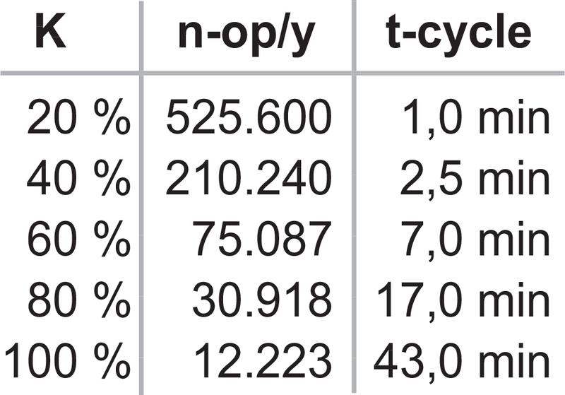
| Mechanical life, minimum | 10,000,000 Operations |
| Mounting | Snaps onto standard DIN rail to EN 60715 |
Mechanical data - Connection technique
| Terminal designations | IEC/EN 60947-1 |
| Cable section, minimum | 0.25 mm² |
| Cable section, maximum | 2.5 mm² |
| Tightening torque of Clips | 0.6 Nm |
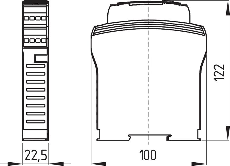
Mechanical data - Dimensions
| Width | 22.5 mm |
| Height | 100 mm |
| Depth | 121 mm |
Ambient conditions
| Degree of protection of the enclosure | IP40 |
| Degree of protection of the mounting space | IP54 |
| Degree of protection of clips or terminals | IP20 |
| Ambient temperature, minimum | -25 °C |
| Ambient temperature, maximum | +60 °C |
| Storage and transport temperature, minimum | -40 °C |
| Storage and transport temperature, maximum | +85 °C |
| Resistance to vibrations to EN 60068-2-6 | 10 ... 55 Hz, Amplitude 0.35 mm |
| Restistance to shock | 30 g / 11 ms |
Ambient conditions - Insulation value
| Rated impulse withstand voltage Uimp | 4 kV |
| Overvoltage category | III |
| Degree of pollution to IEC/EN 60664-1 | 2 |
Electrical data
| Operating Current | 57 mA |
| Rated operating voltage | 24 VDC -15%/+20%, residual ripple max. 10% |
| Rated AC voltage for controls at DC minimum | 20.4 VDC |
| Rated control voltage at DC, maximum | 28.8 VDC |
| Utilisation category AC-15 | 230 VAC |
| Utilisation category AC-15 | 2 A |
| Utilisation category DC-13 | 24 VDC |
| Utilisation category DC-13 | 2 A |
| Electrical power consumption | 3 W |
| Contact resistance, maximum | 0.1 Ω |
| Note (Contact resistance) | in new state |
| Drop-out delay in case of power failure, typically | 20 ms |
| Drop-out delay in case of emergency stop, maximum | 20 ms |
| Pull-in delay at automatic start, maximum, typically | 300 ms |
| Pull-in delay at RESET, typically | 20 ms |
Electrical data - Digital inputs
| Conduction resistance, maximum | 30 Ω |
Electrical data - Electromagnetic compatibility (EMC)
| EMC rating | EMC-Directive |
Other data
| Note (applications) | Safety sensor Guard system Emergency-Stop button Pull-wire emergency stop switches |
Notes
| Note (General) | Inductive loads (e.g. contactors, relays, etc.) are to be suppressed by means of a suitable circuit. |
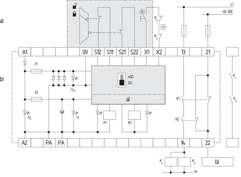
Circuit example
| Note (Wiring diagram) | The wiring diagram is shown with guard doors closed and in de-energised condition. Monitoring 1 guard door(s), each with a magnetic safety sensor of the BNS range If only one external relay or contactor is used to switch the load, the system can be classified in Control Category 3 to ISO 13849-1, if exclusion of the fault “Failure of the external contactor” can be substantiated and is documented, e.g. by using a reliable down-rated contactor. A second contactor leads to an increase in the level of security by redundant switching to switch the load off. To secure a guard door up to PL e and Category 4 The feedback circuit monitors the position of the contactors KA and KB. Automatic start: The automatic start is programmed by connecting the feedback circuit to the terminals X1/X2. If the feedback circuit is not required, establish a bridge. |
Наш менеджер свяжется с вами в ближайшее время